background image

2546358 (2) - 03/2010

Istruzioni per installazione, uso e manutenzione

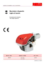
Bruciatore di gasolio
Light oil burner

Funzionamento bistadio
Two stage operation

CODICE - CODE

MODELLO - MODEL

TIPO - TYPE

3092047

RL 70 HS

2047 D

RL 100 HS

I

GB

Summary of Contents for RL 100 HS

Page 1: ...03 2010 Istruzioni per installazione uso e manutenzione Bruciatore di gasolio Light oil burner Funzionamento bistadio Two stage operation CODICE CODE MODELLO MODEL TIPO TYPE 3092047 RL 70 HS 2047 D RL 100 HS I GB ...

Page 2: ......

Page 3: ...ria secondaria 6 Impianto idraulico 7 Impianto elettrico 8 Pompa 10 Regolazione bruciatore 11 Funzionamento bruciatore 12 Controlli finali 13 Manutenzione 13 Diagnostica programma di avviamento 14 Sblocco apparecchiatura e utilizzo diagnostica 14 Inconvenienti Cause Rimedi 15 Status su richiesta 16 Avvertenza Le figure richiamate nel testo sono così indicate 1 A Particolare 1 della figura A nella ...

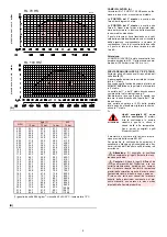
Page 4: ...ax senza filtro Temperatura gasolio 40 C max con filtro Raccordi di attacco 1 4 pollice Per portate del bruciatore superiori a 80 kg h installare due degasatori in parallelo MODELLO RL 70 HS RL 100 HS TIPO 2047 D POTENZA 1 PORTATA 1 stadio 2 kW 593 830 510 714 50 70 711 1130 612 972 60 95 Mcal h kg h stadio 1 kW 355 474 415 711 Mcal h 306 408 355 612 kg h 30 50 35 60 COMBUSTIBILE GASOLIO potere ca...

Page 5: ...luminoso di blocco e pulsante di sblocco 23 Visore fiamma Vi sono due possibilità di blocco del bruciatore Blocco apparecchiatura l accensione del pul sante led rosso dell apparecchiatura 22 A avverte che il bruciatore è in blocco Per sbloccare premere il pulsante per un tempo compreso tra 1 e 3 secondi Blocco motore per sbloccare premere il pul sante del relè termico 17 A IMBALLO PESO B misure in...

Page 6: ...tore è conforme alle richieste di emis sione previste della norma EN 267 Per garantire la costanza delle emissioni è necessario utilizzare ugelli consigliati e o alter nativi indicati dal Produttore nelle istruzioni ed avvertenze Attenzione Si consiglia di sostituire annualmente gli ugelli durante la manu tenzione periodica Cautela L utilizzo di ugelli differenti da quelli prescritti dal Produttor...

Page 7: ...a bruciatore caldaia deve essere erme tica Per ottenere un corretto funzionamento del bru ciatore il refrattario sul portellone caldaia va preparato in modo opportuno seguendo le indi cazioni riportate in figura C e nella allegata tabella dimensionale L assenza del cono illustrato in figura e la proiezione della testa del brucia tore direttamente in camera di com bustione D causa problemi legati a...

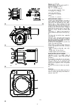
Page 8: ...ome in fig B Rimontare infine il bruciatore 3 C sulle guide 2 e farlo scorrere fino alla flangia 5 tenendolo leggermente sollevato per evitare che lo swirler entri in contrasto con il boccaglio Avvitare le viti 1 sulle guide 2 e le viti 4 che fissano il bruciatore alla flangia Qualora fosse necessario sostituire l ugello con bruciatore già applicato alla caldaia procedere come segue Aprire il bruc...

Page 9: ...Ø Diametro interno tubo 1 Bruciatore 2 Pompa 3 Filtro 4 Valvola manuale intercettazione 5 Condotto di aspirazione 6 Valvola di fondo 7 Valvola manuale a chiusura rapida con comando a distanza solo Italia 8 Elettrovalvola di intercettazione solo Ita lia 9 Condotto di ritorno 10 Valvola di ritegno solo Italia COLLEGAMENTI IDRAULICI B La pompa ha un by pass che mette in comuni cazione il ritorno con ...

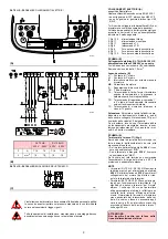
Page 10: ...a 2 stadio VS Elettrovalvola di sicurezza XP1 Connettore per STATUS NOTA In caso sia necessario avere lo sblocco a distanza collegare un pulsante NA fra il mor setto 3 e il neutro dell apparecchiatura morsetti 15 16 17 e 18 RL 70 HS RL 100 HS IMPIANTO ELETTRICO ESEGUITO IN FABBRICA A D3229 L installazione del bruciatore deve essere effettuata da personale abilita to secondo quanto riportato nel pr...

Page 11: ...do TR un ponte tra i mor setti 5 e 6 della morsettiera SCHEMA B Taratura rele termico 17 A p 3 Serve ad evitare la bruciatura del motore per un forte aumento dell assorbimento dovuto alla mancanza di una fase Se il motore è alimentato a stella 400 V il cur sore va posizionato sul MIN Se è alimentato a triangolo 230 V il cursore va posizionato sul MAX Se la scala del relè termico non comprende l as...

Page 12: ...rchio Quando il gasolio fuoriesce dalla vite 3 la pompa è innescata Fermare subito il brucia tore interruttore 1 C p 11 in posizione SPENTO ed avvitare la vite 3 Il tempo necessario per questa operazione dipende dal diametro e dalla lunghezza della tubazione aspirante Se la pompa non si inne sca al primo avviamento e il bruciatore va in blocco attendere circa 15 s sbloccare e ripe tere l avviament...

Page 13: ...er ridurre la portata del combustibile E possibile solo se la temperatura ambiente rimane sopra 0 C Mai scendere sotto i 10 bar il martinetto potrebbe aprirsi con difficoltà 14 bar per aumentare la portata del combusti bile o per avere accensioni sicure anche a tem perature inferiori a 0 C Per variare la pressione della pompa agire sulla vite 5 A p 10 Serranda ventilatore 1 stadio Mantenere il bru...

Page 14: ...sa al teleco mando TR che controlla la pressione o la tem peratura in caldaia Quando la temperatura o la pressione aumenta fino all apertura di TR l elettrovalvola 11 si chiude ed il bruciatore passa dal 2 a 1 stadio di funzionamento Quando la temperatura o la pressione diminuisce fino alla chiusura di TR l elettroval vola 11 si apre ed il bruciatore passa dal 1 al 2 stadio di funzionamento E così...

Page 15: ... condotto Filtri A Controllare i cestelli filtranti di linea 1 in pompa 2 all ugello 3 pulirli o sostituirli Se all interno della pompa si notano ruggine o altre impurità aspirare dal fondo della cisterna con una pompa separata acqua ed altre impu rità eventualmente depositatesi Ventilatore Verificare che all interno del ventilatore e sulle pale della girante non vi sia accumulo di pol vere riduce...

Page 16: ...l funzionamento secondo la codifica indicata nella tabella di pag 15 DIAGNOSTICA SOFTWARE Fornisce l analisi della vita del bruciatore mediante collegamento ottico a PC indicandone ore di funzionamento numero e tipologie di blocchi numero di serie dell apparecchiatura etc Per visualizzare la diagnostica procedere come segue Tenere premuto il pulsante per più di 3 secondi dalla condizione di led ro...

Page 17: ...o stacco fiamma Aumentare portata 1 ugello 39 1 ugello sporco o deformato Sostituirlo 40 Pressione pompa non adatta Regolarla tra 10 e 14 bar 41 Ugello 1 stadio non adatto al bruciatore o alla caldaia Vedere tabella ugelli pag 5 ridurre ugello 1 stadio 42 Ugello 1 stadio difettoso Sostituirlo Il bruciatore non passa in 2 stadio 43 Telecomando TR non chiude Regolarlo o sostituirlo 44 Apparecchiatur...

Page 18: ... inizia il conteggio in sec nel visore V 4 Eccitazione valvola 1 stadio 5 Eccitazione valvola 2 stadio termina il conteggio in sec nel visore V 6 Dopo 10 sec da 5 appare I I I I sul visore la fase di avviamento è terminata CON TERMOSTATO TR APERTO 1 Bruciatore spento termostato TL aperto 2 Chiusura termostato TL 3 Avvio motore inizia il conteggio in sec nel visore V 4 Eccitazione valvola 1 stadio ...

Page 19: ...e assembly 6 Secondary air adjustment 6 Hydraulic system 7 Electrical system 8 Pump 10 Burner calibration 11 Burner operation 12 Final checks 13 Maintenance 13 Burner start up cycle diagnostics 14 Resetting the control box and using diagnostics 14 Fault Probable cause Suggested remedy 15 Status optional 16 N B Figures mentioned in the text are identified as follows 1 A part 1 of figure A same page...

Page 20: ... Light oil temperature max 50 C without filter Light oil temperature max 40 C with filter Attachment connectors 1 4 inch For burner deliveries higher than 80 kg h install two parallel degassing units MODELLO RL 70 HS RL 100 HS TYPE 2047 D OUTPUT 1 DELIVERY 1 2nd stage kW Mcal h kg h 593 830 510 714 50 70 711 1130 612 972 60 95 1st stage kW Mcal h kg h 355 474 306 408 30 50 415 711 355 612 35 60 FU...

Page 21: ...rner failure may occur Control box lock out if the control box 22 A pushbutton red led lights up it indicates that the burner is in lock out To reset hold the pushbutton down for between 1 and 3 seconds Motor trip release by pressing the pushbutton on thermal cutout 17 A PACKAGING WEIGHT B Approximate measurements The burner stands on a wooden base which can be lifted by fork lifts Outer dimension...

Page 22: ...nozzles Monarch type H0 The burner complies with the emission requirements of the EN 267 standard In order to guarantee that emissions do not vary recommended and or alternative nozzles specified by the Manufacturer in the instruction and warning booklet should be used Warning It is advisable to replace nozzles every year during regular maintenance operations Caution The use of nozzles other than ...

Page 23: ... com pounds graphite The burner boiler seal must be airtight In order to obtain a correct burner operation the refractory on the boiler door has to be prepared in an opportune way following the indications of figure F and the attached dimensions table The absence of the cone indicated in the figure and the projection of the burner head directly in the combustion chamber D could cause problems to t...

Page 24: ...ake sure that the electrodes are positioned as shown in Figure B Finally remount the burner 3 C to the slide bars 2 and slide it up to the flange 5 keeping it slightly raised to prevent the swirler disk from pressing against the blast tube Tighten the screws 1 on the slide bars 2 and screws 4 fixing the burner to the flange If it proves necessary to change a nozzle with the burner already fitted t...

Page 25: ...e Key A H Pump Foot valve height difference L Piping length Ø Inside pipe diameter 1 Burner 2 Pump 3 Filter 4 Manual on off valve 5 Suction line 6 Foot valve 7 Rapid closing manual valve remote con trolled only Italy 8 On off solenoid valve only Italy 9 Return line 10 Check valve only Italy HYDRAULIC CONNECTIONS B The pumps are equipped with a by pass that connects return line with suction line Th...

Page 26: ...ut TA Ignition transformer TB Burner ground earth connection V1 1st stage solenoid valve V2 2nd stage solenoid valve VS Safety solenoid valve XP1 Connector for STATUS NOTE For remote reset connect a push button switch NA between terminal 3 and neutral of the con trol box terminals 15 16 17 and 18 RL 70 HS RL 100 HS ELECTRICAL EQUIPMENT FACTORY SET A D3229 The installation of the burner must be car...

Page 27: ...e operation is re quired instead of control device TR install a jumper lead between terminal 11 and 12 of the terminal strip LAYOUT C Calibration of thermal cut out 17 A p 3 This is required to avoid motor burn out in the event of a significant increase in power absorp tion caused by a missing phase If the motor is star powered 400 V the cursor should be positioned to MIN If the motor is delta pow...

Page 28: ...hen the light oil starts coming out of the screw 3 Stop the burner switch 1 C p 11 set to OFF and tighten the screw 3 The time required for this operation depends upon the diameter and length of the suction tub ing If the pump fails to prime at the first starting of the burner and the burner locks out wait ap prox 15 seconds reset the burner and then re peat the starting operation as often as requ...

Page 29: ...d justment is possible only if the surrounding temperature remains above 0 C Never cali brate to pressures below 10 bar at which pres sures the cylinders may have difficulty in opening 14 bar order to increase fuel delivery or to en sure firings even at temperatures of less than 0 C In order to adjust pump pressure use the rele vant screw 5 A p 10 1st stage fan air gate valve Keep the burner opera...

Page 30: ... stage solenoid valve pass es on to the control device TR that controls boiler temperature or pressure When the temperature or the pressure increas es until the control device TR opens solenoid valve 11 closes and the burner passes from the 2nd to the 1st stage of operation When the temperature or pressure decreases until the control device TR closes solenoid valve 11 opens and the burner passes f...

Page 31: ...replace as required If rust or other impurities are observed inside the pump use a separate pump to lift any water and other impurities that may have deposited on the bottom of the tank Then clean the insides of the pump and the cover sealing surface Fan Check to make sure that no dust has accumulat ed inside the fan or on its blades as this condi tion will cause a reduction in the air flow rate a...

Page 32: ...the malfunction according to the coding system indicated in the table on page 15 SOFTWARE DIAGNOSTICS Reports burner life by means of an optical link with the PC indicating hours of operation number and type of lock outs serial number of control box etc To view diagnostics proceed as follows Hold the button down for more than 3 seconds once the red LED burner lock out remains steadily lit A yellow...

Page 33: ... is too big pulsation Reduce 1st nozzle delivery 38 1st nozzle is too small flame detachment Increase 1st nozzle delivery 39 1st nozzle dirty or deformed Replace 40 Inappropriate pump pressure Adjust to between 10 and 14 bar 41 1st stage nozzle unsuited to burner or boiler See Nozzle Table page 12 reduce 1st stage 42 Defective 1st stage nozzle Replace The burner does not pass to 2nd stage 43 Contr...

Page 34: ...stops on read out V 6 10 seconds after stage 5 the code I I I I will appear on the read out this indicates that the starting phase is terminated WITH CONTROL DEVICE TR OPEN 1 Burner off TL open 2 Control device TL closed 3 Motor start seconds count starts on read out V 4 1st stage valve energized 7 30 seconds after stage 4 seconds count stops on read out V 8 10 seconds after stage 7 the code I I I...

Page 35: ......

Page 36: ...RIELLO S p A I 37045 Legnago VR Tel 39 0442 630111 http www riello it http www rielloburners com Con riserva di modifiche Subject to modifications ...

Reviews: