8
ELECTRICAL SYSTEM
ELECTRICAL SYSTEM
factory set
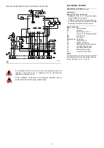
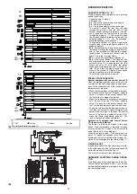
LAYOUT (A)
Burners RL 70 HS - RL 100 HS
• Models RL 70 HS - 100 - 130 leave the factory
preset for
400 V
power supply.
• If
230 V
power supply is used, change the mo-
tor connection from star to delta and change
the setting of the thermal cut-out as well.
Key to Layout (A)
CMV
- Motor contactor
FR
- Photocell
I1
- Switch: burner off - on
I2
- Switch: 1st - 2nd stage operation
MB
- Terminal strip
MV
- Fan motor
RMO88.53A2 - Control box
RT
- Thermal cut-out
TA
- Ignition transformer
TB
- Burner ground (earth) connection
V1
- 1st stage solenoid valve
V2
- 2nd stage solenoid valve
VS
- Safety solenoid valve
XP1
- Connector for STATUS
NOTE
For remote-reset, connect a push-button switch
(NA) between terminal 3 and neutral of the con-
trol box (terminals 15, 16, 17 and 18).
RL 70 HS - RL 100 HS
ELECTRICAL EQUIPMENT FACTORY-SET
(A)
D3229
The installation of the burner must be carried out by qualified personnel, as
indicated in this manual and in compliance with the standards and
regulations of the laws in force.
All the installation, maintenance and disassembly operations must be
carried out with the electricity supply disconnected.
WARNING
DANGER


