Installation
19
20035606
GB
4.8
Nozzles
The burner complies with the emission requirements of the EN 267
standard.
In order to guarantee that emissions do not vary, recommended
and/or alternative nozzles specified by the manufacturer in the In-
struction and warning booklet should be used.
4.8.1
Recommended nozzle
–
BERGONZO, type B5;
–
FLUIDICS, type N1 or W2.
Intermediate flow rates may be obtained by choosing the nozzle
with a nominal flow rate slightly higher than that actually required.
Complete range of nozzles:
Bergonzo B5 60° - 150 - 200 - 225 - 250 - 275 - 300 - 325 - 350 -
375 - 400 - 425.
We normally recommend 60° angles of pulverisation.
4.8.2
Choice of nozzle
Nozzles with or without fuel shutoff needle can be fitted on the noz-
zle holder.
To set the delivery range within which the nozzle must work, nozzle
return line fuel pressure must be adjusted according to the Tab. H.
Ugello CMB 60° B5
Tab. H
4.8.3
Nozzle installation
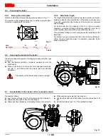
Fit the nozzle with the box spanner, fitting the spanner through the
central hole in the flame stability disk (Fig. 14).
4.9
Electrode and ignition pilot positioning
WARNING
It is advisable to replace nozzles every year during
regular maintenance operations.
CAUTION
The use of nozzles other than those specified by
the manufacturer and inadequate regular mainte-
nance may result into emission limits non-conform-
ing to the values set forth by the regulations in
force, and in extremely serious cases, into potential
hazards to people and objects.
The manufacturing company shall not be liable for
any such damage arising from nonobservance of
the requirements contained in this manual.
kg/h
Delivery
pressure
Return
pressure
kg/h
GPH
150
21
13
51
15.8
Low fire
21
19
106
32.9
High fire
200
22
8.5
67
20.8
Low fire
22
17.5
150
46.6
High fire
300
20
7
100
31.1
Low fire
20
17.5
257
79.9
High fire
375
20
6.5
148
46
Low fire
20
15.5
305
94.8
High fire
425
20
7.5
68
21.1
Low fire
20
17.5
365
113.4
High fire
WARNING
Do not use any sealing products such as gas-
kets, sealing compound, or tape.
Be careful to avoid damaging the nozzle seal-
ing seat.
The nozzles must be screwed into place tightly
but not to the maximum torque value provided
by the wrench.
WARNING
Make sure that the electrode and the ignition pilot
are positioned as shown in Fig. 14.
25/ 32"
1- 13/ 32"
Fig. 14
D11236
Summary of Contents for RL 300
Page 2: ......
Page 33: ...Appendix Spare parts 31 20035606 GB A Appendix Spare parts ...
Page 38: ...20035606 36 GB Appendix Electrical panel layout ...
Page 39: ...Appendix Electrical panel layout 37 20035606 GB ...
Page 41: ...Appendix Electrical panel layout 39 20035606 GB ...
Page 42: ...20035606 40 GB Appendix Electrical panel layout ...
Page 43: ...Appendix Electrical panel layout 41 20035606 GB 0 1 0 ...
Page 44: ...20035606 42 GB Appendix Electrical panel layout 0 0 0 1 0 2 0 0 0 0 0 0 0 30 3 3 0 0 1 0 ...


