20035606
26
GB
Start-up, calibration and operation of the burner
5.1
Notes on safety for the first start-up
5.2
Adjustments before first firing
The optimum calibration of the burner requires an analysis of the
flue gases at the boiler outlet.
Adjust successively:
–
Combustion head
–
Nozzles
–
Pump pressure
Combustion head
The adjustment of the combustion head already carried out
(page 20) need not be altered unless the delivery of the burner is
changed.
Nozzles
See “Nozzles” on page 19.
Pump pressure
20 bar: this is the pressure calibrated in the factory which is usually
sufficient for most purposes. In order to adjust pump pressure, use
the screw 5)(Fig. 22, page 23).
5.3
Burner firing
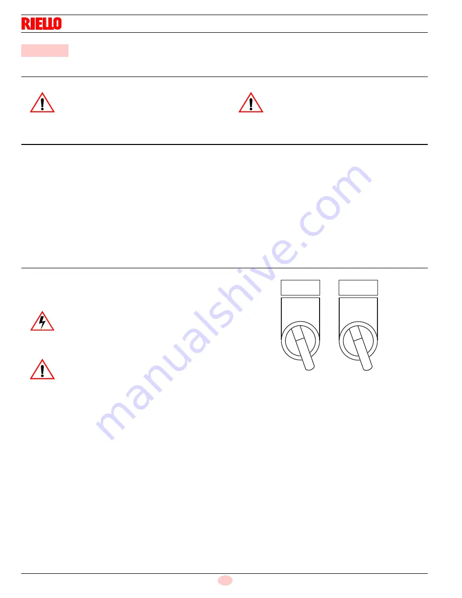
Set the selector to "
ON
" position (Fig. 29).
Close the thermostats/pressure switches and set the selector to
“
LOCAL
”position (Fig. 29).
Having completed the checks indicated in the previous heading,
the burner should fire.
If the motor starts but the flame does not appear and the control
box goes into lock-out, reset and wait for a new firing attempt.
The ignition of the burner is always using the pilot ignition; if firing
is still not achieved, it may be that gas is not reaching the combus-
tion head within the safety time period. In this case increase gas fir-
ing delivery.
Happened this operation, the oil burner active devices and retires
gas operation; if firing is still not achieved, it may be that oil is not
reaching the combustion head within the safety time period. In this
case increase oil firing delivery.
During the first firing, there is a momentary lowering of the fuel
pressure caused by the filling of the nozzle tubing. This lowering of
the fuel pressure can cause the burner to lock-out and can some-
times give rise to pulsations.
Once the following adjustments have been made, the firing of the
burner must generate a noise similar to the noise generated during
operation.
5
Start-up, calibration and operation of the burner
WARNING
The first start-up of the burner must be carried out
by qualified personnel, as indicated in this manual
and in compliance with the standards and regula-
tions of the laws in force.
WARNING
Check the correct working of the adjustment, com-
mand and safety devices.
DANGER
Make sure that the lamps or testers connected to
the solenoids, or indicator lights on the solenoids
themselves, show that no voltage is present.
If voltage is present, stop the burner
immediately
and check the electrical wiring.
WARNING
For the start-up procedure and the parameters
calibration, refer to the specific instruction
manual of the LMV51... electronic cam sup-
plied with the burner.
OFF
ON
REMOTE
LOCAL
Fig. 29
S8323
Summary of Contents for RL 300
Page 2: ......
Page 33: ...Appendix Spare parts 31 20035606 GB A Appendix Spare parts ...
Page 38: ...20035606 36 GB Appendix Electrical panel layout ...
Page 39: ...Appendix Electrical panel layout 37 20035606 GB ...
Page 41: ...Appendix Electrical panel layout 39 20035606 GB ...
Page 42: ...20035606 40 GB Appendix Electrical panel layout ...
Page 43: ...Appendix Electrical panel layout 41 20035606 GB 0 1 0 ...
Page 44: ...20035606 42 GB Appendix Electrical panel layout 0 0 0 1 0 2 0 0 0 0 0 0 0 30 3 3 0 0 1 0 ...


