20035606
28
GB
Start-up, calibration and operation of the burner
5.6
Pressure switches calibration
5.6.1
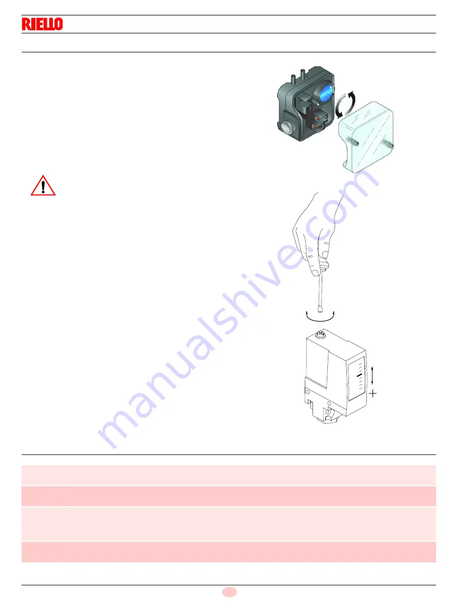
Air pressure switch
Adjust the air pressure switch after having performed all other burn-
er adjustments with the air pressure switch set to the start of the
scale (Fig. 31).
With the burner operating at min. output, increase adjustment pres-
sure by slowly turning the relative dial clockwise until the burner
locks out.
Then turn the dial anti-clockwise by about 20% of the set point and
repeat burner starting to ensure it is correct.
If the burner locks out again, turn the dial anti-clockwise a little bit
more.
5.6.2
Low oil pressure switch
The low oil pressure switch (Fig. 32) is factory set to 261 PSI.
If the oil pressure goes down this value in the delivery piping, the
pressure switch stops the burner.
Burner starts again automatically if the pressure goes above
261 PSI (18 bar) after burner start up.
5.7
Final checks (with the burner working)
WARNING
As a rule, the air pressure switch must prevent the
air pressure from lowering below 80% of the adjust-
ment value as well as preventing the CO in the
fumes from exceeding 1% (10,000 ppm).
To check this, insert a combustion analyser into the
chimney, slowly close the fan suction inlet (for ex-
ample with cardboard) and check that the burner
locks out, before the CO in the fumes exceeds 1%.
Fig. 31
D3854
Fig. 32
-
+
-
D10627
Open the control limit operation
Open the high limit operation
Æ
The burner must stop
Rotate the air pressure switch knob to the maximum end of
scale position
Æ
The burner must stop in lockout
Switch off the burner and disconnect the voltage
Disconnect the minimum gas pressure switch
Rotate the low oil pressure switch at the maximum of the
scale
Æ
The burner must not start
Disconnect the QRI sensor
Æ
The burner must stop in lockout due to firing failure
Summary of Contents for RL 300
Page 2: ......
Page 33: ...Appendix Spare parts 31 20035606 GB A Appendix Spare parts ...
Page 38: ...20035606 36 GB Appendix Electrical panel layout ...
Page 39: ...Appendix Electrical panel layout 37 20035606 GB ...
Page 41: ...Appendix Electrical panel layout 39 20035606 GB ...
Page 42: ...20035606 40 GB Appendix Electrical panel layout ...
Page 43: ...Appendix Electrical panel layout 41 20035606 GB 0 1 0 ...
Page 44: ...20035606 42 GB Appendix Electrical panel layout 0 0 0 1 0 2 0 0 0 0 0 0 0 30 3 3 0 0 1 0 ...


