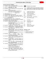
Technical description of the burner
7
20035606
GB
3.3
Burner dimensions
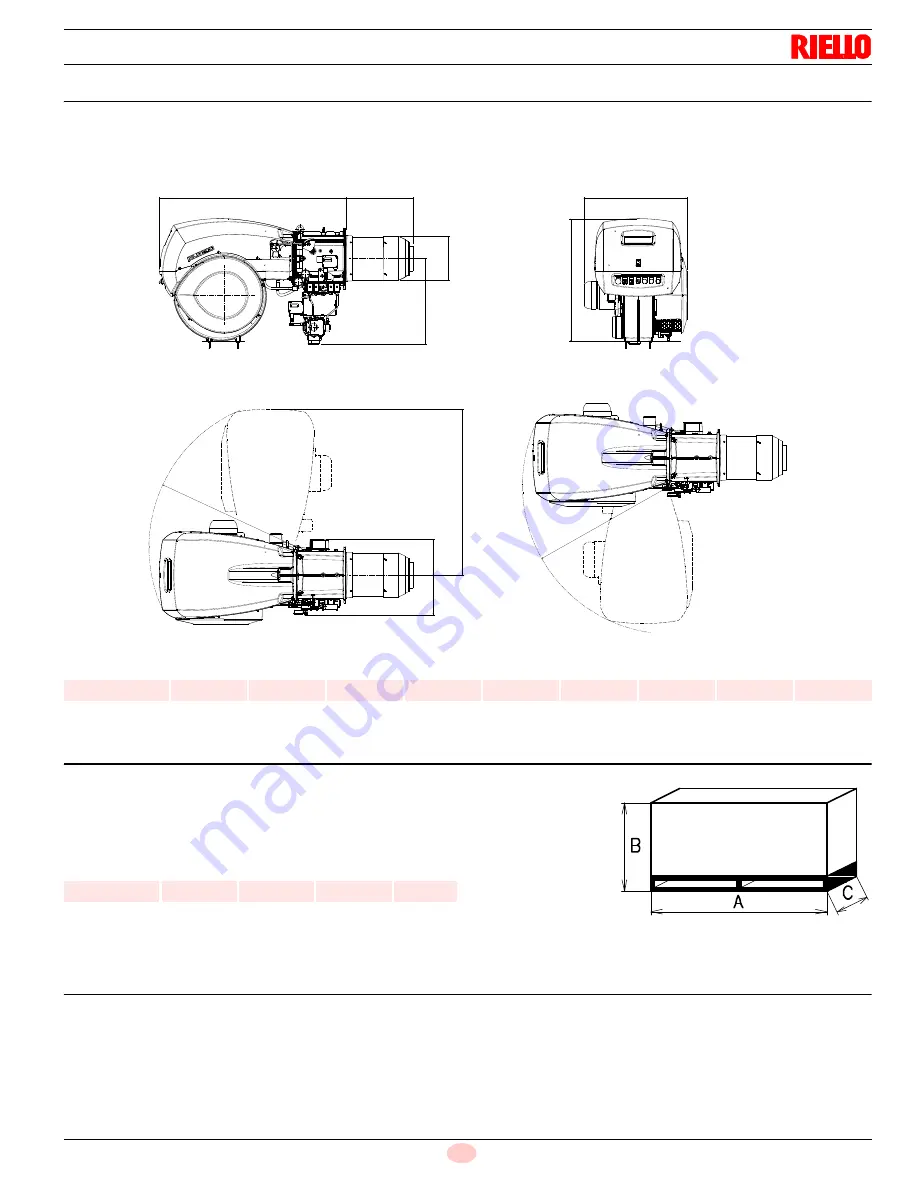
The maximum dimensions of the burner are given in Fig. 1.
Bear in mind that inspection of the combustion head requires the
burner to be opened by rotating the rear part on the hinge.
The overall dimensions of the burner when open are indicated by L
and R.
Tab. B
3.4
Packaging - weight
- Approximate measurements
The burners stands on a wooden base which can be lifted by fork-
lifts. Outer dimensions of packaging are indicated in Fig. 2.
The weight of the burner complete with packaging is indicated in
Tab. C.
Tab. C
3.5
Standard equipment
1 - Thermal insulation screen
4 - Screws to secure the burner flange to the boiler: M 18 x 70
2 - Spacers (see Fig. 18, page 20)
1 - Instruction booklet and spare parts list
D
A
E
B
R
L
S
S
H
G
R
Fig. 1
D8388
mm
A
B
D
E
G
H
L
R
S
RL 300/E
52
3/16”
20
1/2”
12
5/16”
23
5/32”
28
11/32”
34
9/64”
14
1/32”
41
17/32”
12
19/32”
inch
A
B
C
lbs
RL 300/E
77
11/64”
37
1/64”
38
3/16”
496
Fig. 2
D36
Summary of Contents for RL 300
Page 2: ......
Page 33: ...Appendix Spare parts 31 20035606 GB A Appendix Spare parts ...
Page 38: ...20035606 36 GB Appendix Electrical panel layout ...
Page 39: ...Appendix Electrical panel layout 37 20035606 GB ...
Page 41: ...Appendix Electrical panel layout 39 20035606 GB ...
Page 42: ...20035606 40 GB Appendix Electrical panel layout ...
Page 43: ...Appendix Electrical panel layout 41 20035606 GB 0 1 0 ...
Page 44: ...20035606 42 GB Appendix Electrical panel layout 0 0 0 1 0 2 0 0 0 0 0 0 0 30 3 3 0 0 1 0 ...


