6423
22
GB
Electrical system
7.2
Electrical wiring
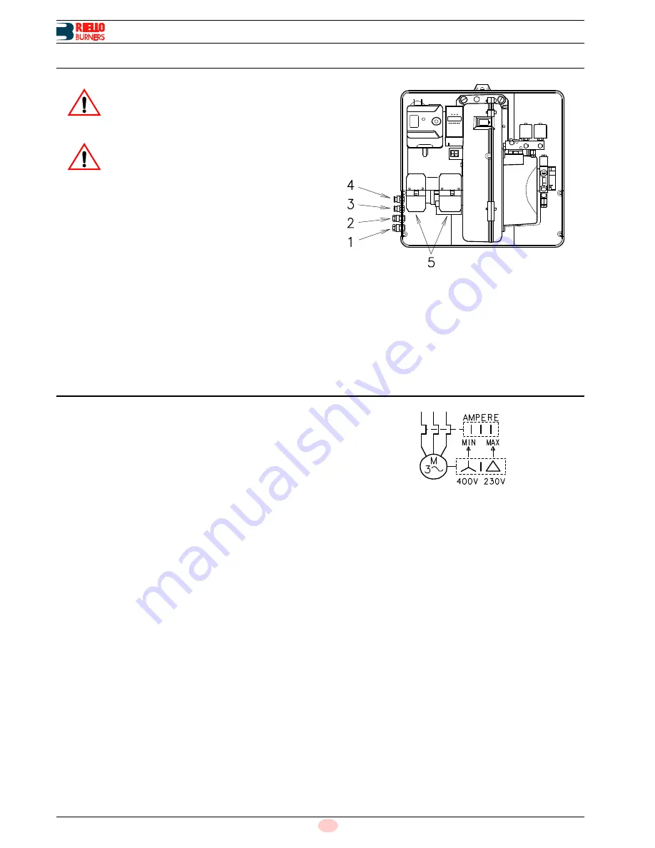
All the cables to be connected to the burner sockets 5)(Fig. 22)
must be routed through the fairleads, supplied by the manufactur-
er for insertion into the holes in the plate, preferably those on the
left side, after having removed the thin diaphragm effectively
closing the aperture, as already explained above.
1 - Pg 11 Three-phase power supply
2 - Pg 11 Power supply
3 - Pg 9 Control device TL
4 - Pg 9 Control device TR
NOTE
Burners leave the factory preset for
400V
power supply. If
230V
power supply is used, change the motor connection
from star to delta and change the setting of the thermal cut-
out as well.
7.3
Thermal relay calibration
This is required to avoid motor burn-out in the event of a signifi-
cant increase in intake power caused by a missing phase.
If the motor is star-powered,
400V
, the cursor should be posi-
tioned at "MIN".
If the motor is delta-powered,
230V
, the cursor should be posi-
tioned at "MAX".
Even if the scale of the thermal relay does not include rated motor
input power at 400V, protection is still ensured in any case.
WARNING
Use flexible cables according to standard EN 60
335-1:
• if in PVC boot, use at least H05 VV-F
• if in rubber boot, use at least H05 RR-F.
WARNING
–
Do not invert the neutral with the phase wire
in the electricity supply line. Any inversion
would cause a lockout due to firing failure.
–
Only use original spare parts to replace the
components.
D465
Fig. 22
D867
Fig. 23


