background image

3

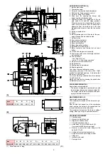
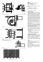
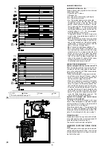
BURNER DESCRIPTION (A)

1 Ignition electrodes
2 Combustion head
3 Screw for combustion head adjustment
4 Photocell for flame presence control
5 Screw for fixing fan to flange
6 Slide bars for opening the burner and

inspecting the combustion head

7 Hydraulic cylinder for regulation of the air

gate valve in 1st and 2nd stage positions.
When the burner is not operating the air gate
valve is fully closed in order to reduce heat
dispersion from the boiler due to the flue
draught which draws air from the fan suction
inlet.

8 Safety solenoid valve
9 Pump
10 Plate prearranged to drill 4 holes for the pas-

sage of hoses and electrical cables.

11 Air inlet to fan
12 Fan pressure test point
13 Boiler mounting flange
14 Flame stability disk
15 Flame inspection window
16 Extensions for slide bars 6)
17 Motor contactor and thermal cut-out reset

button

18 1st and 2nd stage valve assembly
19 Control box with lock-out pilot light and lock-

out reset button

20 Two switches:

- one “burner off - on”
- one for “1st - 2nd stage operation”

21 Plugs for electrical connections
22 Air gate valve
23 Pump pressure adjustment
24 Engine protection

Two types of burner failure may occur:
Control box lock-out

if the control box 19)(A)

pushbutton (

red led

) lights up, it indicates that

the burner is in lock-out.
To reset, hold the pushbutton down for between
1 and 3 seconds.
Motor trip: release by pressing the pushbutton
on thermal cutout 17)(A).

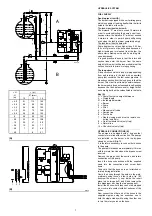
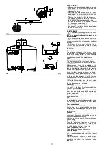
PACKAGING-WEIGHT (B) 

Approximate measurements
• The burner is shipped in cardboard boxe with

the maximum dimensions shown in table (B).

• The weight of the burner complete with pack-

aging is indicated in table (B). 

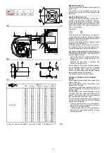
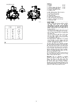
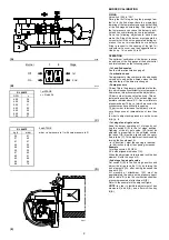
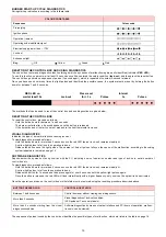
MAX. DIMENSIONS (C)

Approximate measurements.
The maximum dimensions of the burner are giv-
en in (C).
Bear in mind that inspection of the combustion
head requires the burner to be opened and the
rear part withdrawn on the slide bars.
The maximum dimension of the burner, without
casing, when open is give by measurement I.

STANDARD EQUIPMENT

2 - Flexible hoses
2 - Gaskets for flexible hoses
2 - Nipples for flexible hoses
1 - Thermal insulation screen
2 - Extensions 16)(A) for slide bars 6)(A)

(for model with 385 mm blast tube)

4 - Screws to secure the burner flange to the

boiler: M 12 x 35

4 - Fairleads for electrical connections
1 - Engine protection (with fixing screws)
1 - Plugs unit
1 - Instruction booklet
1 - Spare parts lis

(A)

(B)

(C)

8

1 1

1 0

1 2 1 3

1 4

2

3

4

5

6

7

9

1

D

C

B

A

I

G

E

F

H

L

mm

A

B

C

kg

RL 64 MZ

1200

520

580

42

(1)

Blast tube: short - lang

mm

A

B

C

D

E

F

(1)

G

H

I

(1)

L

RL 64 MZ

533 300 238 490 477 250 - 385 179 335 680 - 815

60

D3260

D7460

D7459

D88

D7461

Summary of Contents for RL 64 MZ

Page 1: ...iento Instruções de Instalação Funcionamento e Manutenção Light oil burners Quemadores de gasóleo Queimadores a gasóleo Two stage operation Funcionamiento a dos llamas Funcionamento a duas chamas 2916278 6 03 2010 CODE CÓDIGO MODEL MODELO TYPE TIPO 3470410 RL 64 MZ 974 T 3470411 RL 64 MZ 974 T GB E P ...

Page 2: ......

Page 3: ...or user or to another system If the manual is lost or damaged another copy must be requested from the Technical Assistance Service of the area is designed for use by qualified personnel offers important indications and instructions relating to the instal lation safety start up use and maintenance of the burner DELIVERY OF THE SYSTEM AND THE INSTRUCTION MANUAL When the system is delivered it is imp...

Page 4: ...ntermittent min 1 stop in 24 hours Two stage high and low flame and single stage all nothing NOZZLES number 2 STANDARD APPLICATIONS Boilers water steam diathermic oil AMBIENT TEMPERATURE C 0 40 COMBUSTION AIR TEMPERATURE C max 60 ELECTRICAL SUPPLY V Hz 230 400 with neutral 10 50 three phase ELECTRIC MOTOR rpm W V A 2800 1500 220 240 380 415 4 7 2 7 IGNITION TRASFORMER V1 V2 I1 I2 230 V 2 x 12 kV 0...

Page 5: ... lock out if the control box 19 A pushbutton red led lights up it indicates that the burner is in lock out To reset hold the pushbutton down for between 1 and 3 seconds Motor trip release by pressing the pushbutton on thermal cutout 17 A PACKAGING WEIGHT B Approximate measurements The burner is shipped in cardboard boxe with the maximum dimensions shown in table B The weight of the burner complete...

Page 6: ...and length of the test combustion chamber Example Delivery 35 kg hour diameter 50 cm length 1 5 m Whenever the burner is operated in a much smaller commercially available combustion chamber a preliminary test should be per formed INSTALLATION THE BURNER MUST BE INSTALLED IN CONFORMITY WITH LEGISLATION AND LOCAL STANDARDS WORKING POSITION C The burner is designed to work only in the positions 1 2 3...

Page 7: ...R 1st AND 2nd STAGE Both nozzles must be chosen from among those listed in table D The first nozzle determines the delivery of the burner in the 1st stage The second nozzle works together with the 1st nozzle to determine the delivery of the burner in the 2nd stage The deliveries of the 1st and 2nd stages must be contained within the value range indicated on page 2 Use nozzles with a 60 spray angle...

Page 8: ... bars 3 and slide it up to the flange 5 keeping it slightly raised to prevent the flame stability disk from pressing against the blast tube Tighten the screws 2 on the slide bars 3 and screw 1 that attaches the burner to the flange If it proves necessary to change a nozzle with the burner already fitted to the boiler proceed as outlined below Retract the burner on its slide bars as shown in fig B ...

Page 9: ...pe diameter 1 Burner 2 Pump 3 Filter 4 Manual on off valve 5 Suction line 6 Foot valve 7 Rapid closing manual valve remote con trolled only Italy 8 On off solenoid valve only Italy 9 Return line 10 Check valve only Italy HYDRAULIC CONNECTIONS B The pumps are equipped with a by pass that connects return line with suction line The pumps are installed on the burner with the by pass closed by screw 6 ...

Page 10: ...he pump can be considered to be primed when the light oil starts coming out of the screw 3 Stop the burner switch 1 B p 9 set to OFF and tighten the screw 3 The time required for this operation depends upon the diameter and length of the suction tub ing If the pump fails to prime at the first starting of the burner and the burner locks out wait ap prox 15 seconds reset the burner and then re peat ...

Page 11: ...ures the cylinders may have difficulty in opening 14 bar in order to increase fuel delivery or to en sure firings even at temperatures of less than 0 C In order to adjust pump pressure use the screw 5 A p 8 1st stage fan air gate valve Keep the burner operating at 1st stage by set ting the switch 2 B to the 1st stage position Opening of the air gate valve 1 A must be adjusted in proportion to the ...

Page 12: ...d stage solenoid valve pass es on to the control device TR that controls boiler temperature or pressure When the temperature or the pressure increas es until the control device TR opens solenoid valve 11 closes and the burner passes from the 2nd to the 1st stage of operation When the temperature or pressure decreases until the control device TR closes solenoid valve 11 opens and the burner passes ...

Page 13: ...either the suction piping or the pump If the pump is found to be responsible check to make sure that the filter is not dirty The vacuum meter is installed upstream from the filter and consequently will not indicate whether the filter is clogged or not Contrarily if the problem lies in the suction line check to make sure that the filter is clean and that air is not entering the piping Filters A Che...

Page 14: ...amber pressure TO OPEN THE BURNER D Switch off the electrical power Remove screw 1 and withdraw the casing 2 Unscrew screw 3 Fit the two extensions 4 supplied with the burner onto the slide bars 5 model with 385 mm blast tube Pull part A backward keeping it slightly raised to avoid damaging the disk 6 on blast tube 7 Fuel pump and or couplings replacement E In conformity with fig E D E D486 D1108 ...

Page 15: ...the malfunction according to the coding system indicated in the table on page 14 SOFTWARE DIAGNOSTICS Reports burner life by means of an optical link with the PC indicating hours of operation number and type of lock outs serial number of control box etc To view diagnostics proceed as follows Hold the button down for more than 3 seconds once the red LED burner lock out remains steadily lit A yellow...

Page 16: ...oo small flame detachment Increase 1st nozzle delivery 38 1st nozzle dirty or deformed Replace 39 Inappropriate pump pressure Adjust to between 10 and 14 bar 40 1st stage nozzle unsuited to burner or boiler See Nozzle Table page 5 reduce 1st stage 41 Defective 1st stage nozzle Replace The burner does not pass to 2nd stage 42 Control device TR does not close Adjust or replace 43 Defective control b...

Page 17: ...age valve energized seconds count stops on read out V 6 10 seconds after stage 5 the code I I I I will appear on the read out this indicates that the starting phase is terminated WITH CONTROL DEVICE TR OPEN 1 Burner off TL open 2 Control device TL closed 3 Motor start seconds count starts on read out V 4 1st stage valve energized 7 30 seconds after stage 4 seconds count stops on read out V 8 10 se...

Page 18: ...iginate from the light oil itself as a consequence of depressurization or air leaking past imperfect seals In double pipe systems the air returns to the tank from the return pipe in single pipe systems the air remains in circulation causing pressure var iations in the pump and burner malfunctions For this reason we advise installing a degassing unit near the burner in single pipe installations Deg...

Page 19: ... on MAX If the scale of the thermal cutout does not include the absorption of rating of the motor at 400V the protection is guaranteed anyway Burners leave the factory preset for 400 V power supply If 230 V power supply is used change the motor connection from star to delta and change the setting of the thermal cutout as well The burners have been type approved for intermittent operation This mean...

Page 20: ......

Reviews: