20045163
28
GB
Start-up, calibration and operation of the burner
5.5
Final calibration of the pressure switch
5.5.1
Air pressure switch
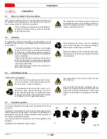
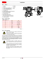
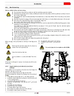
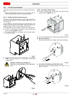
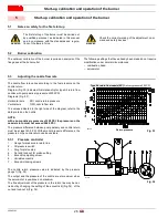
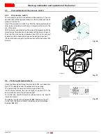
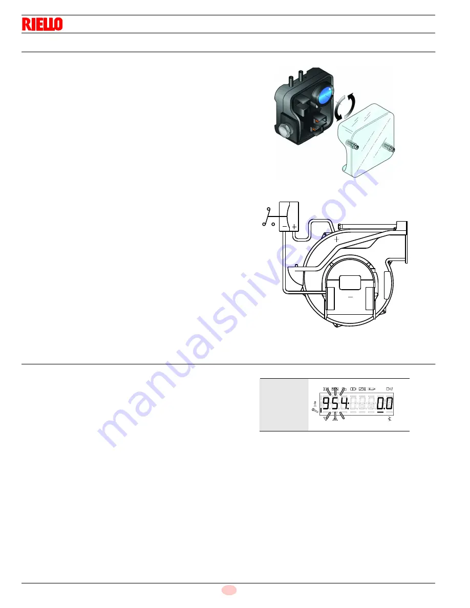
The air pressure switch is connected in differential (Fig. 37) and is
activated by both the negative pressure of the air intake and the air
pressure from the fan.
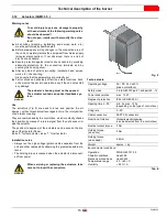
Adjust the air pressure switch (Fig. 36) after having performed all
other burner adjustments with the air pressure switch set to the
min. of the scale.
With the burner operating at low fire, adjust the pressure switch by
slowly turning the relative knob clockwise until the burner locks out.
Then turn the knob counter-clockwise about 20% of the set point
and start-up the burner again to ensure the set point is correct.
If the burner locks out again, turn the knob counter-clockwise a little
bit more.
5.6
Flame signal measurement
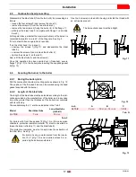
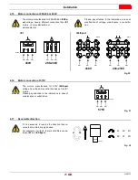
Check the flame signal through the parameter 954, as indicated in
Fig. 38. The displayed value is expressed in percentage.
The value during the operation must be higher than 24%.
If at the burner start-up the value is higher or equal of 18%, the
burner locks out due to the extraneous light.
For further and specific information, please refer to the specific
instruction manual.
The display (Fig. 38) shows parameter 954: flashing on the left.
On the right, the flame’s intensity is displayed as a percentage.
Example: 954: 0.0
Fig. 36
D3854
Fig. 37
20048352
S8171
P
V
h
min s
%
Fig. 38

