20045163
8
GB
Technical description of the burner
3.6
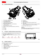
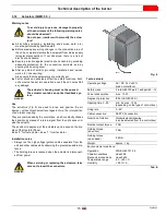
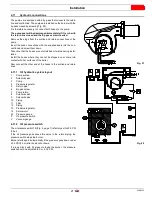
Panel board description
1
"OFF - LOCAL - REMOTE" switch
2
"ALARM SILENCE" button
3
Low air pressure switch
4
Operator panel with LCD display
5
Burner terminal board "X1"
6
Control box for checking flame and air/fuel ratio
7
Ignition transformer
8
Terminal strip "X2" for oil valve
9
Fan motor contactor and thermal relay with reset button
10
Horn
11
"K4" relay
12
"K3" relay
13
"K1" relay
14
"K2" relay
15
Optional hole
16
Ground terminals
17
RWF 40 modulator (with analog output 4-20 mA)
18
UV scanner
19
Holes for cables grommets for electrical wirings, accessories
and power supply (to be carried out by the installer)
One type of burner failure may occur:
Motor trip
Release by pressing the pushbutton on thermal overload 9)(Fig. 3).
See “Thermal relay calibration” on page 24.
3.7
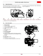
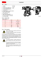
Packaging - weight (approximate measurements)
➤
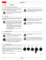
The burners is supplied skid mounted. Outer dimensions of
packaging are indicated in (Fig. 4).
➤
The weight of the burner complete with packaging is indicated
in table.
3.8
Standard equipment
The burner is supplied complete with:
2 - Flexible hoses
2 - Gaskets for flexible hoses
1 - Burner head gasket
4 - Screws to secure the burner flange to the boiler
1/2
W
1 - Adaptor G
1/8
“ /
1/8
“ NPT
1 - Instruction booklet
1 - Spare parts list
Fig. 3
D12231
inch
A
B
C
lbs
RL 70/E
45
9/32“
23
5/8“
31
3/16“
143
D36
Fig. 4


