20045163
22
GB
Installation
4.12
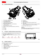
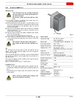
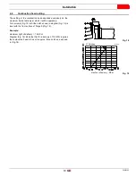
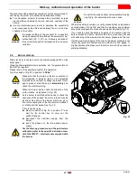
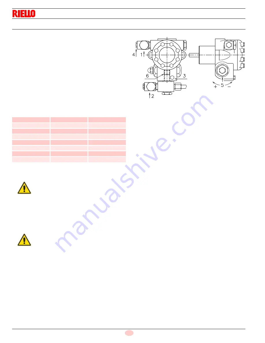
Pump
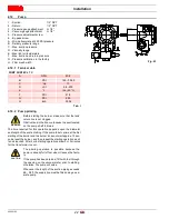
1 - Suction
1/2" NPT
2 - Return
1/2" NPT
3 - Pressure gauge attachment
G 1/8"
4 - Vacuum gauge attachment
G 1/8"
5 - Pressure adjustment screw
6 - By-pass screw
A - Min. delivery rate at 290 PSI pressure
B - Delivery pressure range
C - Max. suction pressure
D - Viscosity range
E - Max light oil temperature
F - Max. suction and return pressure
G - Pressure calibration in the factory
H - Filter mesh width
4.12.1 Tecnical data
Tab. I
4.12.2 Pump priming
The time required for this operation depends upon the diameter
and length of the suction tubing. If the pump fails to prime at the first
starting of the burner and the burner locks out, wait approx. 15 sec-
onds, reset the burner, and then repeat the starting operation as of-
ten as required. After 5 or 6 starting operations allow 2 or 3 minutes
for the transformer to cool.
PUMP SUNTEC J7 C
A
GPH
60.8
B
PSI
145 - 304.5
C
“Hg
13
D
cSt
2,8 - 200
E
°F
194 (90 °C)
F
PSI
21.8
G
PSI
290
H
inch
0,006
WARNING
Before starting the burner, make sure that the tank
return line is not clogged.
Obstructions in the line could cause the seal located
on the pump shaft to break.
CAUTION
The priming operation is possible because the
pump is already full of fuel when it leaves the facto-
ry.
If the pump has been drained, fill it with fuel through
the opening on the vacuum meter prior to starting;
otherwise, the pump will seize.
Whenever the length of the suction piping exceeds
66 - 98 ft, the supply line must be filled using a sep-
arate pump.
D2352
Fig. 23

