background image

33 

20067636

GB

Start-up, calibration and operation of the burner

6.8

Combustion air adjustment

Fuel/combustion air synchronisation is done with the relevant
servomotors (air and gas) by logging a calibration curve by
means of the electronic cam.

It is advisable, to reduce the loss and for a wide calibration field,
to adjust the servomotors to the maximum of the output used, the
nearest possible to the maximum opening (90°).

On the gas butterfly valve, fuel step according to the burner out-
put required, with servomotor completely open, is carried out by
the pressure stabiliser placed on the gas train.

The values indicated in Tab. J and Tab. K can be a reference for
a good combustion calibration.

Tab. J

Tab. K

6.8.1

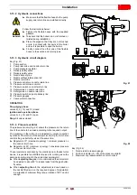
Air / gas adjustment and output modulation

The air/gas adjustment and output modulation system with which
the 

RLS

 range burners are equipped carries out a series of inte-

grated functions in order to optimise burner functioning, both for
single operation and together with other units (e.g. double fur-
nace boiler or more than one generator in parallel).

The basic system functions control:
1

The dosage of the air and fuel through positioning using
direct servo commands of the relevant valves eliminating
the possible play in the calibration systems with mechanical
cam lever mechanisms, used on traditional modulating
burners.

2

The modulation of the burner output in accordance with the
load required by the system, with maintenance of the pres-
sure or temperature of the boiler at the operating values set.

3

The sequence (cascade adjustment) of more than one
boiler through the suitable connection of the various units
and the activation of the internal software of the individual
systems (option).

Further interfaces and communication functions with computers,
for remote control or integration in central supervision systems
are available on the basis of the configuration of the system.

The first start-up and curve synchronisation manual is supplied
with the burner.

At request, the complete manual for the control and setting of all
parameters is available.

EN 676

Air excess

CO

Max. output


 1.2

Max. output


 1.3

GAS

Theoretical max 

CO

2

0 % O

2

CO

2

 % Calibration

mg/kWh

 = 1.2

 = 1.3

G 20

11.7

9.7

9

 1000

G 25

11.5

9.5

8.8

 1000

G 30

14.0

11.6

10.7

 1000

G 31

13.7

11.4

10.5

 1000

EN 267

Air excess

CO

Max. output




1.2

Min. output




1.3

Theoretical max CO

2

0 % O

2

CO

2

 % Calibration

mg/kWh

 = 1.2

 = 1.3

15.2

12.6

11.5

 1000

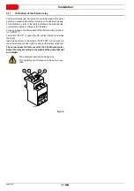
WARNING

The first start up and every further internal setting
operation of the adjustment system or the expan-
sion of the base functions require access by
means of password and are to be carried out by
service personnel who are especially trained for
the internal programming of the instrument and
the specific application created with this burner.

Summary of Contents for RLS 1600/EV C11

Page 1: ...Installation use and maintenance instructions 20067636 1 12 2016 Dual fuel light oil gas burners Modulating operation CODE MODEL TYPE 20080869 RLS 1600 EV C11 LS003T2 20066055 RLS 2000 EV C11 1316 T2 GB ...

Page 2: ...Original instructions ...

Page 3: ...cription 12 4 12 Burner equipment 12 4 13 AZL Display 13 4 14 Control box for the air fuel ratio LMV52 14 4 15 Servomotor SQM48 4 16 5 Installation 17 5 1 Notes on safety for the installation 17 5 2 Handling 17 5 3 Preliminary checks 17 5 4 Operating position 18 5 5 Removing the shutter lockout screws 18 5 6 Coupling of the burner Centre of gravity position 18 5 7 Preparing the boiler 19 5 7 1 Bor...

Page 4: ...rt up gas 32 6 6 Burner ignition 32 6 7 Change of fuel 32 6 8 Combustion air adjustment 33 6 8 1 Air gas adjustment and output modulation 33 6 9 Pressure switch adjustment 34 6 9 1 Air pressure switch check CO 34 6 9 2 Maximum gas pressure switch 34 6 9 3 Minimum gas pressure switch 34 6 9 4 PVP pressure switch kit 34 6 9 5 Oil pressure switch 35 6 10 Final checks with burner operating 35 7 Mainte...

Page 5: ...patibility Such products are marked as follows The quality is guaranteed by a quality and management system certified in accordance with UNI EN ISO 9001 Manufacturer s Declaration RIELLO S p A declares that the following products comply with the NOx emission limits specified by German standard 1 BIm SchV revision 26 01 2010 Product Type Model Output Dual fuel light oil gas burners LS003T2 RLS 1600...

Page 6: ...ied out correctly may cause damage to the ma chine and or injury to people DANGER DANGER LIVE COMPONENTS This symbol indicates operations which if not car ried out correctly lead to electric shocks with le thal consequences DANGER FLAMMABLE MATERIAL This symbol indicates the presence of flammable materials DANGER BURNING This symbol indicates the risks of burns due to high temperatures DANGER CRUS...

Page 7: ...event of damage to things or injury to people if such damage injury was due to any of the following causes incorrect installation start up use and maintenance of the burner improper incorrect or unreasonable use of the burner intervention of unqualified personnel carrying out of unauthorised modifications on the equipment use of the burner with safety devices that are faulty incor rectly applied a...

Page 8: ...maintenance Only those parts envisaged by the manufacturer can be replaced 3 2 Personnel training The user is the person body or company that has acquired the machine and intends to use it for the specific purpose He is re sponsible for the machine and for the training of the people work ing around it The user undertakes to entrust the machine exclusively to suitably trained and qualified personne...

Page 9: ...l supply of the system 3 400 50 3 230 50 Voltage of auxiliaries 230 50 60 110 50 60 R LS 1600 EV TC Emission C11 or Class 1 EN267 EN676 C22 or MZ Class 2 EN267 EN676 C33 or BLU Class 3 EN267 EN676 FS1 3 400 50 230 50 60 BASIC DESIGNATION EXTENDED DESIGNATION C11 3N 400V 50Hz 3 230V 50Hz 230V 50 60Hz 110V 50 60Hz Heavy oil E Electronic cam SV Electronic cam with variable speed with Inverter P Propo...

Page 10: ...x kW kg h 3065 9503 15560 4000 12000 19500 Fuels Light oil max viscosity at 20 C 6 mm2 s 1 5 E 6 cSt Natural gas G20 methane gas G21 G22 G23 G25 Gas pressure at max output 2 Gas G20 G25 mbar 145 5 190 Operation 3 Intermittent Continuous min 1 stop every 24 72 hours Modulating Nozzles number 1 Standard applications Boilers water steam diathermic oil Ambient temperature C 0 50 Combustion air tempera...

Page 11: ...he combustion head requires the burn er to be opened and the rear part turned on the hinge The maximum dimensions of the open burner are indicated by the L and R positions The l position is reference for the refractory thickness of the boiler door Tab E Burner kg Burner packaging kg 1100 approx 1180 1 7 0 0 2600 1080 1710 Fig 1 20124100 C D I B A F E R L R G H Fig 2 20124101 mm A B C D E F G H I L...

Page 12: ...The firing rates were set in relation to special test boilers according to EN 676 regulations In Fig 4 you can see the diameter and length of the test combus tion chamber Example Output 7000 kW diameter 120 cm length 6 m MODULATING RATIO The modulating ratio obtained in the test boilers according to standard EN 676 for gas EN 267 for light oil is of 4 1 WARNING The firing rate value Fig 3 has been...

Page 13: ...essure test point 21 QRI cell 22 Pressure test point for air pressure switch 23 Gas butterfly valve and oil modulator servomotor 24 Delivery pressure gauge 25 Oil delivery safety valves 26 Maximum oil pressure switch on return 27 Minimum oil pressure switch 28 Combustion head gas pressure test point 29 Rpm probe 30 Return oil safety valves 31 Shutter position adjustment servomotor 32 Screws to loc...

Page 14: ...ket pump motor derivation unit 22 Plug socket servomotor 23 Pump motor contactor and thermal relay 24 Off automatic selector 25 Rpm sensor terminal board NOTE Two types of burner failure may occur Control box lockout the switching on of the button red led 13 Fig 6 signals that the burner is in lockout Release by pressing button 13 Fig 6 or use the display Motor lockout release the pump motor by pr...

Page 15: ...r data Technical data Tab F WARNING To avoid accidents material or environmental damage observe the following instructions The AZL display is a safety device Avoid open ing or modifying it or forcing its operation Riello S p A cannot assume any responsibility for dam age resulting from unauthorised interventions Operating voltage AC 24 V 15 10 Power consumption 5W typical Protection level of the c...

Page 16: ... also be followed avoid conditions that can favour the development of conden sate and humidity Otherwise before switching on again make sure that the entire control box is perfectly dry Static charges must be avoided since they can damage the control box s electronic components when touched Mechanical structure The LMV5 control box is a system to check the burners based on a microprocessor and equ...

Page 17: ...C 188 V Oil pump magnetic clutch nominal voltage Nominal current Power factor 2A cos 0 4 Air pressure switch test valve nominal voltage Nominal current Power factor 0 5A cos 0 4 Load on output terminals Total load on the contacts Mains voltage Total unit input current safety circuit load on contacts due to Fan motor contactor Ignition transformer Valve Oil pump magnetic clutch AC 230 V 15 10 Max 5...

Page 18: ... low voltage section The static torque is reduced when the electrical supply of the actuator is switched off The housing cover may only be removed for short periods of time for wiring or when making the addressing In similar cas es make sure that dust or dirt does not penetrate inside the actuator The actuator comprises a PCB with ESD sensitive compo nents The top side of the board carries a cover...

Page 19: ...ler must be free from hazardous mixes e g chloride fluoride halo gen if present it is highly recommended to carry out cleaning and maintenance more frequently WARNING The handling operations for the burner can be highly dangerous if not carried out with the great est attention keep any unauthorised people at a distance check the integrity and suitableness of the available means of handling Check a...

Page 20: ... 2 3 and 4 Fig 11 Installation 1 is preferable as it is the only one that allows the maintenance operations as described in this manual Installations 2 3 and 4 permit operation but make maintenance and inspection of the combustion head more difficult DANGER Any other position could compromise the cor rect operation of the appliance Installation 5 is prohibited for safety reasons Fig 11 2 3 4 5 1 2...

Page 21: ...rotection device in refractory material 5 must be inserted between the boiler fettling 2 and the blast tube 4 This protective fettling must not compromise the extraction of the blast tube For boilers with a water cooled front piece a refractory lining 2 5 Fig 15 is not necessary unless expressly requested by the boiler manufacturer 5 8 Securing the burner to the boiler Insert the thermal protectio...

Page 22: ...the trans former 13 and remove it by unscrewing the fitting 14 unscrew the 4 fixing screws of the pipe coupling 4 open the burner on the hinge disconnect the cable of the pilot electrode 5 release the ignition pilot fitting 6 disconnect the light oil pipes 7 unscrew the lockout screw 9 of the oil lance 10 extract the oil lance 10 from the combustion head 11 extract the combustion head of the head ...

Page 23: ...e a year during periodical maintenance CAUTION The use of nozzles other than those specified by Riello S p A and inadequate regular maintenance may result into emission limits non conforming to the values set forth by the regulations in force and in extremely serious cases into potential hazards to people and objects The manufacturing company shall not be liable for any such damage arising from no...

Page 24: ...ct operation of the sys tem The pump unit models available in combination with these burners are indicated in the final pages of this instruction book let 4 Fig 19 20124119 WARNING The gas pipes leave the factory calibrated at notch 1 The adjustment shown in Fig 20 allows the gas pipes to be positioned in the best way for the ap plication on which the burner is installed e g boil ers with flame in...

Page 25: ...n the nozzle return line Regulator at 90 minimum opening maximum pressure on the nozzle return line The servomotor is controlled by the electronic cam thanks to this device it is possible to set different curves for oil and gas on the same servomotor also for the air damper servomotor When adjusting the gas it is recommended the servomotor be adjusted to about 90 to reduce leaks from the gas butte...

Page 26: ...n control is compulsory for burners with maximum outputs over 1200 kW 9 Gasket for flanged versions only 10 Pressure adjuster 11 Train Burner adaptor supplied separately P2 Upstream pressure of valves adjuster P3 Upstream pressure of the filter L Gas train supplied separately L1 The responsibility of the installer Explosion danger due to fuel leaks in the pres ence of a flammable source Precaution...

Page 27: ...28 Find inTab H related to the burner concerned the pressure value closest to the result of the subtraction Read off the corresponding output on the left Example RLS 1600 EV C11 with natural gas G20 Operation at maximum modulating output Gas pressure at test point 1 Fig 28 46 mbar Pressure in combustion chamber 5 mbar 46 5 41 mbar A pressure of 41 mbar column 1 corresponds in Tab H to an output of...

Page 28: ...ressure required at test point 1 Fig 28 5 14 5 Pilot gas train connection The burner is fitted with a dedicated gas train that is fixed to the pipe coupling It should be connected to the main train downstream the fil ter or the pressure adjuster depending on configuration 5 14 6 Ignition pilot burner For proper operation adjust gas pressure measured at pressure test point 1 Fig 29 as follows Tab I...

Page 29: ...ponds to that shown on the identification label and in this man ual The burner has been type approved for intermittent operation FS1 This means that it should as a rule be stopped at least once every 24 hours to enable the control box to perform checks of its own start up efficiency Normally burner stopping is guaranteed by the boiler s thermostat pressure switch If this is not the case a time swi...

Page 30: ... Electrical supply 2 Minimum gas pressure switch 3 Pressure switch for VPS gas valve leak detection 4 Gas train 5 Consents Safety 6 Available 7 Plug 8 Rpm sensor cable outlet DANGER Turn off the burner s electrical supply using the main system switch DANGER Turn off the fuel interception tap DANGER Avoid condensate ice and water leaks from form ing WARNING To guarantee the protection level of the ...

Page 31: ... check then close the motor casing by tightening the 4 screws 1 Fig 33 5 16 Motor rotation As the burner is not fitted with a phase sequence checking de vice the motor rotation may be incorrect If this is not the case turn the burner switch to position 0 OFF and wait for the control box to carry out the switch off phase disconnect the power supply to the main panel invert the phases on the three p...

Page 32: ... case of an intervention of the thermal relay press but ton RESET 1 The button STOP 3 opens the NC contact 95 96 and stops the motor Insert a screwdriver in the window TEST TRIP 4 and move it in the arrow direction to the right to carry out the thermal relay test The burner leaves the factory set for the 5 5 kW pump motor Adjust the relay according to the output of the pump that will be installed ...

Page 33: ...irst ignition there is a momentary drop in fuel pressure due to the filling of the nozzle piping This lowering of the fuel pressure can cause the burner to lockout and can sometimes give rise to pulsations Once the following adjustments have been made the ignition of the burner must generate a noise similar to the noise generated during operation If a burner lockout occurs refer to the Release pro...

Page 34: ...ate that no volt age is present If voltage is present stop the burner immediately and check the electrical connections When the limit thermostat TL closes the CALL FOR HEAT 3 signal must come on The burner will subsequently begin its start ing cycle 6 6 Burner ignition The burner should light after having performed the above steps If the motor starts up but the flame does not appear and the con tr...

Page 35: ...am lever mechanisms used on traditional modulating burners 2 The modulation of the burner output in accordance with the load required by the system with maintenance of the pres sure or temperature of the boiler at the operating values set 3 The sequence cascade adjustment of more than one boiler through the suitable connection of the various units and the activation of the internal software of the...

Page 36: ... switch Adjust the maximum gas pressure switch after having performed all the other burner adjustments with the maximum gas pressure switch set at the end of the scale Fig 40 With the burner operating at maximum output lower the adjust ment pressure by slowly turning the relative knob anticlockwise until the burner locks out Turn the knob clockwise by 0 2 kPa 2 mbar and repeat the start up of the ...

Page 37: ...Any other pressure values should be adjusted to the burner out put 6 10 Final checks with burner operating Tab L Fig 43 20079898 Open the thermostat pressure switch TL Open the thermostat pressure switch TS The burner must stop Turn the gas maximum pressure switch knob to the mini mum end of scale position Turn the air pressure switch to the maximum end of scale position The burner must stop in lo...

Page 38: ...ad regulation of the burner In order to measure use a voltmeter with a 10V DC scale con nected as in the diagram Fig 44 Burner Clean the outside of the burner Fan Check to make sure that no dust has accumulated inside the fan or on its impellers as this condition will cause a reduction in the air flow rate and provoke polluting combustion Boiler Clean the boiler as indicated in its accompanying in...

Page 39: ...good conditions Fuel tank Approximately every 5 years suck any water on the bottom of the tank using a separate pump Combustion In case the combustion values found at the beginning of the inter vention do not respect the standards in force or in any case do not correspond to a proper combustion contact the Technical As sistance Service in order to carry out the necessary adjustments Tab M Gas leak...

Page 40: ...specified life cycles do not refer to the warranty terms indi cated in the delivery or payment conditions Tab O 7 2 6 Pump unit DANGER Turn off the burner s electrical supply using the main system switch WARNING Failure to install the control panel 1 in the seat of the electrical panel results in the machine s loss of IP protection WARNING In the event the rpm sensor is malfunctioning or needs rep...

Page 41: ...possible to open the burner on the hinge 7 4 Closing the burner Refit following the steps described but in reverse order refit all burner components as they were originally assembled DANGER Turn off the burner s electrical supply using the main system switch DANGER Turn off the fuel interception tap Wait for the components in contact with heat sources to cool down completely 2 1 Fig 48 20124127 Af...

Page 42: ...rts again the red LED goes out and the con trol box is reset 8 Faults Probable causes Solutions WARNING In the event the burner stops in order to prevent any damage to the installation do not unblock the burner more than twice in a row If the burner locks out for a third time contact the customer service DANGER In the event there are further lockouts or faults with the burner the maintenance inter...

Page 43: ...odels 3010388 Burner Code All models 20045187 Burner Power Supply Inverter Output Code RLS 1600 EV C11 3Ph 400V 50Hz 37 kW 20095475 RLS 2000 EV C11 3Ph 400V 50Hz 45 kW 20095476 WARNING The use of inverters other than those indicated by the manufacturer may lead to burner failure and in extreme cases a potential risk of harm to people and damage to property The manufacturing company shall not be li...

Page 44: ... Model Fuel Connection Output at 30 bar Motor kW Burner max output kg h Code SG 1000 Light oil 1 2200 l h 4 900 20097693 SG 1250 Light oil 1 3000 l h 4 1250 20098501 SG 1500 Light oil 1 3600 l h 5 5 1500 20097701 SG 2000 Light oil 1 4800 l h 7 5 2000 20097703 ...

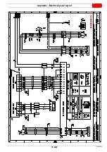
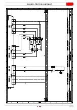
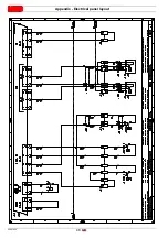
Page 45: ...6 LMV52 functional layout 7 LMV52 functional layout 8 LMV52 functional layout 9 LMV52 functional layout 10 LMV52 functional layout 11 LMV52 functional layout 12 LMV52 functional layout 13 Electrical wiring that the installer is responsible for 14 Electrical wiring that the installer is responsible for 15 Electrical wiring that the installer is responsible for 1 2 Sheet no 1 A1 Co ordinates Indicat...

Page 46: ... 0 869 9 9 AB 9 C 9 9 9 6 1 1 1 6 D 4 1 4 4 0 1 20 2 4 4 0 869 05 6 E 8 E 8 D D D D 6 1 8 1 F 1 1 1 1 F 2 2 0 3 4 F 2 4 2 G 1 F H F 2 2 21 2 0 F 2 0 2 F 2 2 2 2 F 2 2 2 2 2 4F 2 4 1 F 2 2 2 F 2 2 2 2 2 F 1 0 1 12 1 12 1 1 F 2 4 F 2 4 2 G 1 1 F 2 2 2 1 2 20 1 1 1 1 2 4 0 1 1 2 2 6 2 2 2 1 1 I I RLS 1600 EV C11 ...

Page 47: ... 0 869 9 9 AB 9 C 9 9 9 6 1 1 1 6 D 4 1 4 4 0 1 20 2 4 4 0 869 05 6 E 8 E 8 D D D D 6 1 8 1 F 1 1 1 1 F 2 2 0 3 4 F 2 4 2 G 1 F H F 2 2 21 2 0 F 2 0 2 F 2 2 2 2 F 2 2 2 2 2 4F 2 4 1 F 2 2 2 F 2 2 2 2 2 F 1 0 1 12 1 12 1 1 F 2 4 F 2 4 2 G 1 1 F 2 2 2 1 2 20 1 1 1 1 2 4 0 1 1 2 2 6 2 2 2 1 1 I I RLS 2000 EV C11 ...

Page 48: ...20067636 46 GB Appendix Electrical panel layout 0 0 0 0 0 0 0 0 ...

Page 49: ...47 20067636 GB Appendix Electrical panel layout ...

Page 50: ...20067636 48 GB Appendix Electrical panel layout 0 0 1 2 1 2 3 1 3 4 1 5 1 3 1 3 3 1 1 1 21 2 1 61 6 6 2 1 1 3 4 1 3 ...

Page 51: ...49 20067636 GB Appendix Electrical panel layout ...

Page 52: ...20067636 50 GB Appendix Electrical panel layout 0 1 1 1 ...

Page 53: ...51 20067636 GB Appendix Electrical panel layout 0 1 0 ...

Page 54: ...20067636 52 GB Appendix Electrical panel layout 0 1 1 1 2 1 3 1 1 1 1 1 1 1 41 4 4 1 1 2 1 ...

Page 55: ...53 20067636 GB Appendix Electrical panel layout 0 0 0 1 0 2 0 0 0 0 0 0 0 30 3 3 0 0 1 0 4 ...

Page 56: ...20067636 54 GB Appendix Electrical panel layout 0 0 1 2 0 0 3 3 3 0 1 4 ...

Page 57: ...GB Appendix Electrical panel layout 0 1 2 3 4 5 0 0 60 54 7 0 07 1 0 0 4 4 4 4 2 1 0 0 7 4 0 4 2 4 4 4 2 84 49 49 0 0 0 0 0 0 0 0 0 0 0 0 3 3 4 6 2 2 0 5 0 4 4 2 2 0 3 3 0 4 0 0 0 0 0 3 0 2 2 0 0 0 RLS 1600 EV C11 ...

Page 58: ...GB Appendix Electrical panel layout 0 1 2 3 4 5 0 0 60 54 7 0 07 1 0 0 4 4 4 4 2 1 0 0 7 4 0 4 2 4 4 4 2 84 49 49 0 0 0 0 0 0 0 0 0 0 0 0 3 3 4 6 2 2 0 5 0 4 4 2 2 0 3 3 0 4 0 0 0 0 0 3 0 2 2 0 0 0 RLS 2000 EV C11 ...

Page 59: ...57 20067636 GB Appendix Electrical panel layout 0 1 2 10 3 3 2 4 2 5 0 5 0 0 4 0 0 3 0 4 ਅ 0 4 560 7 7 6 3 8 0 8 0 1 2 2 0 28 9 2 4 4 05 2 4 5 4 1 4 50 4 50 5 4 4 4 4 4 4 0 4 4 5 4 5 ...

Page 60: ...20067636 58 GB Appendix Electrical panel layout ৼ 0 1 1 1 1 1 2 2 2 0 2 2 2 2 2 2 2 2 2 2 2 0 2 3 ...

Page 61: ...n motor PA Air pressure switch PE Burner earth PGMAX Maximum gas pressure switch PGMin Minimum gas pressure switch PGVP Pilot valves gas pressure switch PO Minimum oil pressure switch PO1 Maximum oil pressure switch on return line Q1 Inverter power supply disconnect switch Q2 Line disconnect switch QRI Flame sensor RS Remote burner reset button S1 Emergency stop button S2 0 AUTO selector S5 Fuel s...

Page 62: ......

Page 63: ......

Page 64: ...Subject to modifications RIELLO S p A I 37045 Legnago VR Tel 39 0442 630111 http www riello it http www riello com ...

Reviews: