18
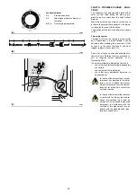
5 - AIR PRESSURE SWITCH (A)
Adjust the air pressure switch after having per-
formed all other burner adjustments with the air
pressure switch set to the start of the scale (A).
With the burner working at MIN output, insert a
combustion analyser in the stack, slowly close
the suction inlet of the fan (for example, with
cardboard) until the CO value does not exceed
100 ppm.
Then slowly turn the appropriate knob clockwise
until the burner reaches the lockout position.
Check the indication of the arrow pointing
upwards on the graduated scale (A). Turn the
knob clockwise again, until the value shown on
the graduated scale corresponds with the arrow
pointing downwards (A), and so recovering the
hysteresis of the pressure switch (shown by the
white mark on a blue background, between the
two arrows).
Now check the correct start-up of the burner.
If the burner locks out again, turn the knob anti-
clockwise a little bit more.
The incorporated air pressure switch can work
in a 'differential' mode if connected with two
pipes. If a negative pressure in the combustion
chamber during pre-purging prevents the air
pressure switch from switching. Switching may
be obtained by fitting a second pipe between the
air pressure switch and the suction inlet of the
fan. In such a manner the air pressure switch
operates as differential pressure switch.
Attention:
the use of the air pressure switch
with differential operation is allowed only in
industrial applications and in places where
national rules enable the air pressure switch to
control only fan operation.
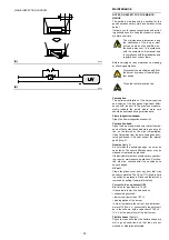
6 - MAXIMUM GAS PRESSURE SWITCH (B)
Adjust the maximum gas pressure switch after
having performed all the other burner adjust-
ments with the maximum gas pressure switch
set at the end of the scale (B).
With the burner operating at MAX output,
reduce the adjustment pressure by slowly turn-
ing the relative knob anticlockwise until the
burner locks out.
Then turn the knob clockwise by 2 mbar and
repeat burner firing.
If the burner locks out again, turn the knob again
clockwise by 1 mbar.
7 - MINIMUM GAS PRESSURE SWITCH (C)
Adjust the minimum gas pressure switch after
having performed all the other burner adjust-
ments with the pressure switch set at the start of
the scale (C).
With the burner operating at MAX output,
increase adjustment pressure by slowly turning
the relative knob clockwise until the burner
locks out.
Then turn the knob anti-clockwise by 2 mbar
and repeat burner starting to ensure it is uni-
form.
If the burner locks out again, turn the knob anti-
clockwise again by 1 mbar.
(A)
(C)
AIR PRESSURE SWITCH
MIN. GAS PRESSURE SWITCH
MAX. GAS PRESSURE SWITCH
(B)
D3951
D3856
D3855
Summary of Contents for RLS 250/M MZ
Page 2: ...Original instructions 说明书原文翻译 ...
Page 29: ...27 0 0 0 0 1 2 33 0 3 1 45 45 67 67 8 2 9 0 0 3 2 ...
Page 30: ...28 0 0 0 1 0 2 0 0 0 0 0 0 0 30 3 3 0 0 1 0 ...
Page 32: ...30 0 1 1 2 2 0 3 4 5 6 3 0 2 7 5 6 4 8 0 5 5 9 4 9 4 1 2 1 ...
Page 36: ......
Page 62: ...26 0 0 0 0 1 2 33 0 3 1 45 45 67 67 8 2 9 0 0 3 2 ...
Page 63: ...27 0 0 0 1 0 2 0 0 0 0 0 0 0 30 3 3 0 0 1 0 ...
Page 65: ...29 0 1 1 2 2 0 3 4 5 6 3 0 2 7 5 6 4 8 0 5 5 9 4 9 4 1 2 1 ...
Page 69: ......
Page 70: ......
Page 71: ......


