33
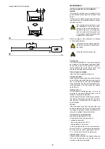
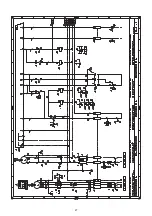
ELECTRICAL CONNECTIONS (A)
Use flexible cables according to EN 60 335-1
regulations.
All the wires to connect to the burner must enter
through the supplied fairleads.
The fairleads and hole press-outs can be used
in various ways; the following lists show one
possible solution:
1 - M25 - Three-phase powersupply
2 - M20 - Single-phase power supply
3 - M20 - Triggering / Safety devices
4 - Available
Cable grommets used in the factory:
A - Fan motor
B - Servomotor
C - Pump motor
D - Safety solenoid
E - 1
st
stage solenoid valve
F - 2
nd
stage solenoid valve
G - Maximum gas pressure switch
H - Flame sensor
The burner has been type- approved for inter-
mittent operation. This means it shoulds com-
pulsorily be stopped at least once every 24
hours to enable the control box to perform
checks of its own efficiency at start-up. Burner
halts are normally provided for automatically by
the boiler load control system.
If this is not the case, a time switch should be fit-
ted in series to IN to provide for burner shut-
down at least once every 24 hours.
Wiring must be performed by qualified
personnel in accordance with the
regulations in force in the country of
destination.
Riello S.p.a. declines all responsibility for
changes or wiring performed in any way
other than that illustrated in these diagrams.
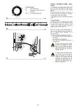
CALIBRATION OF THE THERMAL RELAY (B)
The thermal relay is used to avoid damage to
the motor owing to a strong increase in absorp-
tion or the lack of a phase.
For the calibration
2)
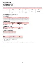
, refer to the table given in
electrical layout (Electrical connections set by
installer).
To reset, in the case of an intervention of the
thermal relay, press the button “RESET”
1)
.
The button “STOP”
3)
opens the NC (95-96)
contact and stops the motor.
To test the thermal relay, insert a screwdriver in
the window “TEST/TRIP”
4)
and move it in the
sense of the arrow (towards right).
Do not invert the neutral with the
phase wire in the electricity sup-
ply line.
Automatic resetting can be dan-
gerous. This action is not pro-
vided for the burner operation.
B
G
4
A
D C
E F
H
4
1
2
4
3
3
4
(A)
D8880
1
2
3
MAN
AUT
O
STOP
NO
98
97
96
95
RESET
NC
4
TEST/TRIP
(B)
D8685
WARNING
WARNING
Summary of Contents for RLS 250/M MZ
Page 2: ...Original instructions 说明书原文翻译 ...
Page 29: ...27 0 0 0 0 1 2 33 0 3 1 45 45 67 67 8 2 9 0 0 3 2 ...
Page 30: ...28 0 0 0 1 0 2 0 0 0 0 0 0 0 30 3 3 0 0 1 0 ...
Page 32: ...30 0 1 1 2 2 0 3 4 5 6 3 0 2 7 5 6 4 8 0 5 5 9 4 9 4 1 2 1 ...
Page 36: ......
Page 62: ...26 0 0 0 0 1 2 33 0 3 1 45 45 67 67 8 2 9 0 0 3 2 ...
Page 63: ...27 0 0 0 1 0 2 0 0 0 0 0 0 0 30 3 3 0 0 1 0 ...
Page 65: ...29 0 1 1 2 2 0 3 4 5 6 3 0 2 7 5 6 4 8 0 5 5 9 4 9 4 1 2 1 ...
Page 69: ......
Page 70: ......
Page 71: ......


