20034293
20
GB
Installation
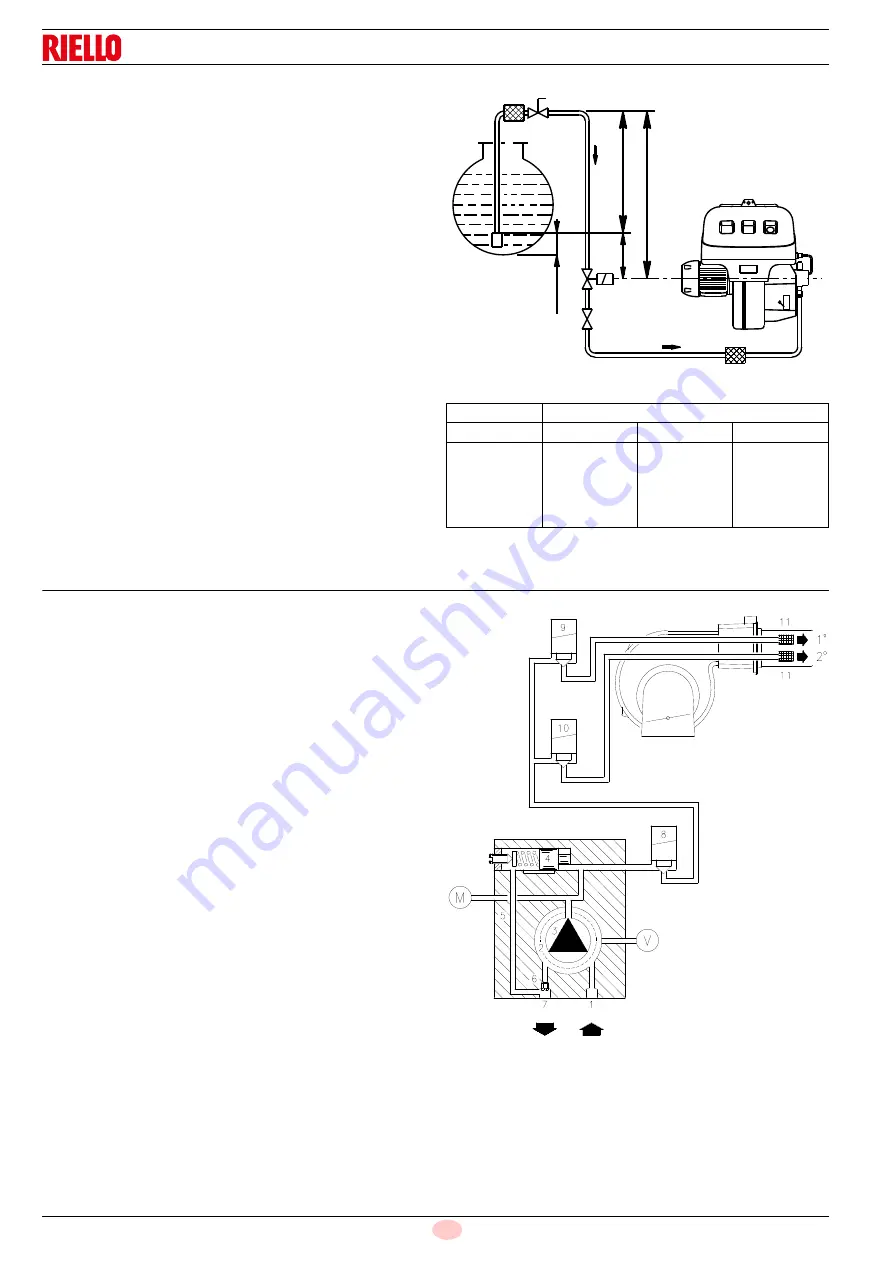
5.12.3 Single-pipe circuit
In order to obtain single-pipe working it is necessary to unscrew
the return hose, remove the by-pass screw 6)(Fig. 19) and then
screw the plug 7)(Fig. 19).
The distance “P” must not exceed 10 meters in order to avoid
subjecting the pump's seal to excessive strain; the distance "V"
must not exceed 4 meters.
For the priming pump loosen the screw 3)(Fig. 21) in order to
bleed off the air contained in the suction line and wait until the fuel
flows out.
Key (Fig. 18)
H Pump/Foot valve height difference
L Piping length
ø Inside pipe diameter
1
Burner
2
Pump
3
Filter
4
Manual on/off valve
5
Suction line
6
Foot valve
7
Rapid closing manual valve remote controlled (only Italy)
8
On/off solenoid valve (only Italy)
11 Tank filter
Tab. L
5.13
Hydraulic system layout
Pump suction
2
Filter
3
Pump
4
Pressure governor
5
Return pipe
6
By-pass screw
7
Pump return
8
Safety solenoid
9
1
st
stage valve
10 2
nd
stage valve
11 Filter
M Pressure gauge
V
Vacuometer
+H L
(meters)
(meters)
ø 8 mm
ø 10 mm
ø 12 mm
4
3
2
1
0.5
71
62
53
44
40
138
122
106
90
82
150
150
150
150
150
Fig. 18
10
c
m
11
5
2
4
6
7
5
P
V
8
+H
1
A
3
D11079
Fig. 19
D3006
Summary of Contents for RLS 250/M
Page 2: ...Original instructions ...
Page 45: ...43 20034293 GB Appendix Electrical panel layout ...
Page 46: ...20034293 44 GB Appendix Electrical panel layout ...
Page 47: ...45 20034293 GB Appendix Electrical panel layout ...
Page 48: ...20034293 46 GB Appendix Electrical panel layout ...
Page 49: ...47 20034293 GB Appendix Electrical panel layout ...
Page 51: ......


