20034293
26
GB
Installation
5.18
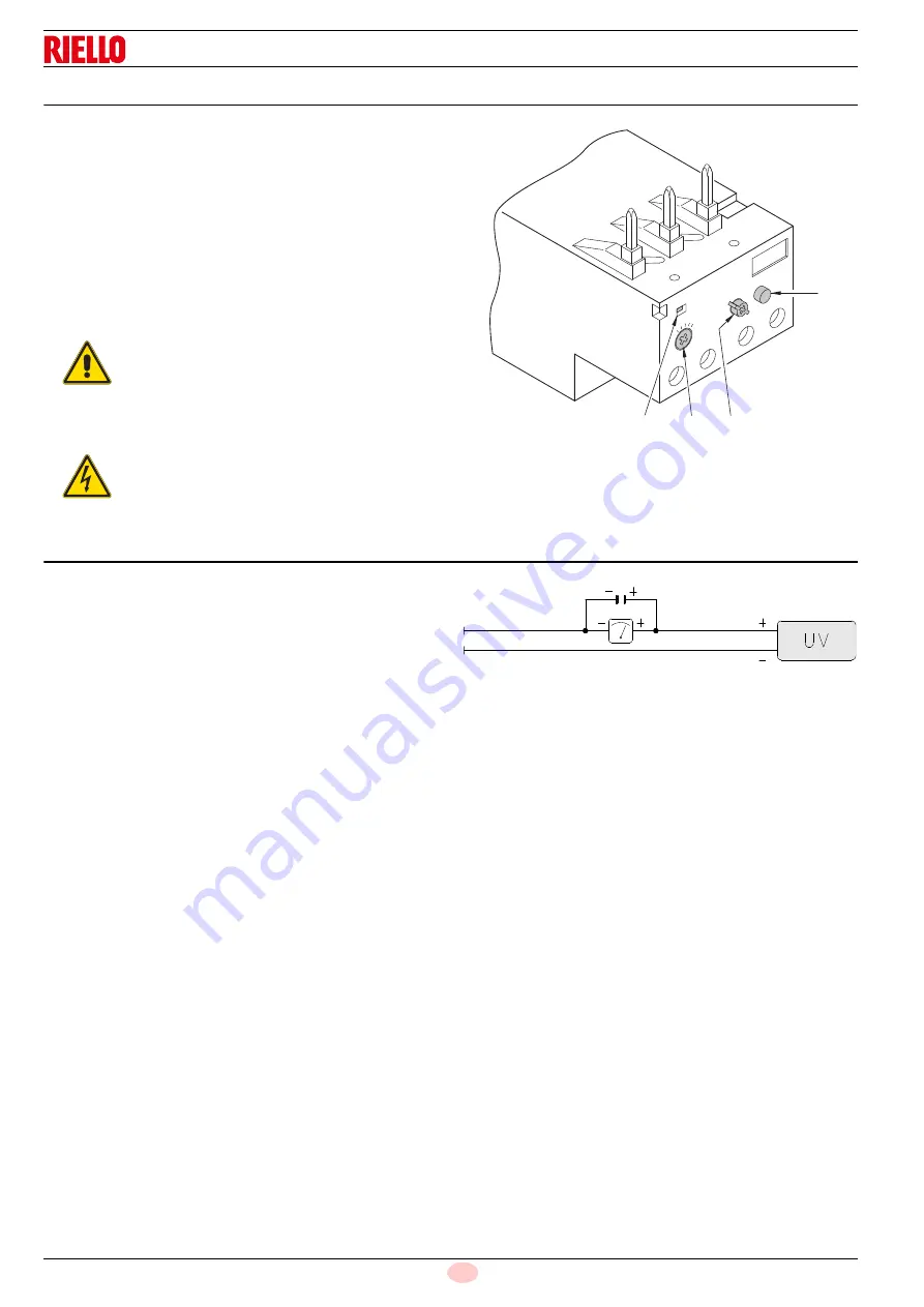
Calibration of thermal relay
The thermal relay (Fig. 27) is used to avoid damage to the motor
owing to a strong increase in absorption or the lack of a phase.
For the calibration 2), refer to the table given in electrical layout
(Electrical connections set by installer).
To reset, in the case of an intervention of the thermal relay, press
the button “RESET” 1).
The button “STOP” 3) opens the NC (95-96) contact and stops
the motor.
To test the thermal relay, insert a screwdriver in the window
“TEST/TRIP” 4) and move it in the sense of the arrow (towards
right).
Before carrying out any maintenance, cleaning or checking oper-
ations:
5.19
Current to the UV photocell
Min. value for a good work: 70 µA.
If the value is lower, it can depend on:
–
exhausted photocell
–
low current (lower than 187V)
–
bad regulation of the burner
In order to measure the current, use a microammeter of 100 µA
c.c., connected to the photocell, as in the scheme, with a capac-
itor of 100 µF - 1V c.c. at the same level of the instrument.
See Fig. 28.
WARNING
Automatic resetting can be dangerous. This ac-
tion is not provided for the burner operation.
DANGER
Disconnect the electricity supply from the burner
by means of the main switch of the system.
Close the fuel interception tap.
1
2
3
MAN
AUT
O
STOP
NO
98
97
96
95
RESET
NC
4
TEST/TRIP
Fig. 27
D8685
Fig. 28
D1143
Summary of Contents for RLS 250/M
Page 2: ...Original instructions ...
Page 45: ...43 20034293 GB Appendix Electrical panel layout ...
Page 46: ...20034293 44 GB Appendix Electrical panel layout ...
Page 47: ...45 20034293 GB Appendix Electrical panel layout ...
Page 48: ...20034293 46 GB Appendix Electrical panel layout ...
Page 49: ...47 20034293 GB Appendix Electrical panel layout ...
Page 51: ......


