23
20085953
GB
Installation
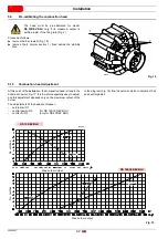
External air R1 adjustment
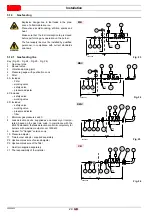
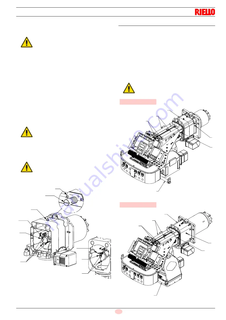
Rotate the screw 4)(Fig. 20) until the notch you have found
corresponds with the front surface 5) of the flange.
Central gas/air R2 adjustment (for RS 120-160/EV BLU)
Loosen the 3 screws 1)(Fig. 20) and rotate the ring nut 2)
until the notch you have found corresponds with the
index 3).
Block the 3 screws 1).
Example:
RS 120/EV BLU, burner output = 850 kW.
The diagram of (Fig. 19) shows that the adjustments for this po-
tential are:
–
air R1
= notch 4
–
central gas/air R2
= notch 3
Central air R3 adjustment (only for RS 200/EV BLU)
Loosen the 2 screws 1) and rotate the ring nut 2) until the
notch you have found corresponds with the screw 1).
Block the 2 screws 1).
NOTE:
the diagram (Fig. 19) indicates the optimum adjustment for a
type of boiler according to Fig. 4.
5.11
Burner closing
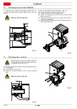
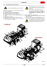
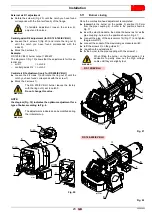
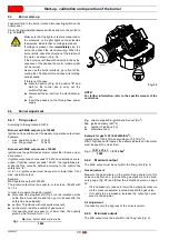
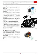
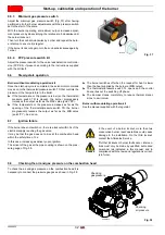
Once the combustion head adjustment is completed:
reassemble the burner on the guides 3) at about 100 mm
from the pipe coupling 4) - burner in the position shown in
Fig. 17;
insert the electrode cable, then slide the burner as far as the
pipe coupling - burner in the position shown in Fig. 21;
connect the plug of the servomotor 14)(Fig. 17) and tighten
the grommet 15);
connect the socket of the maximum gas pressure switch;
refit the screws 2) on the guides 3);
reposition the extensions 6);
fix the burner to the pipe coupling with the screws 1).
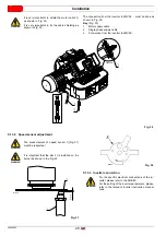
WARNING
To facilitate adjustment, loosen the screw 6),
adjust and then lock.
WARNING
The RS 200/EV BLU burner leaves the factory
with the ring nut 3) set to notch 0.
Do not change this value.
WARNING
The adjustments indicated can be modified during
the initial start-up.
2
(R2)
1
3
6
4
(R1)
5
1
2 (R3)
3
Fig. 20
D7675
WARNING
When fitting the burner on the two guides, it is
advisable to gently draw out the high voltage
cable until they are slightly taut.
1
2
3
4
5
6
20086318
Fig. 21
RS 120/EV BLU
1
2
3
4
5
6
20086386
Fig. 22
RS 160-200/EV BLU
Summary of Contents for RS 120/EV BLU
Page 2: ...Translation of the original instructions ...
Page 43: ...41 20085953 GB Appendix Electrical panel layout ...
Page 45: ...43 20085953 GB Appendix Electrical panel layout ...
Page 46: ...20085953 44 GB Appendix Electrical panel layout ...
Page 47: ...45 20085953 GB Appendix Electrical panel layout ...
Page 54: ......
Page 55: ......


