background image

Installation, use and maintenance instructions

20068118 (2) - 09/2016

Forced draught gas burners

Progressive two-stage or modulating operation

CODE

MODEL

TYPE

3910710

RS 25/E BLU

878 T

3910701 - 3910711

RS 25/E BLU

878 T

3910810

RS 35/E BLU

879 T

3910801 - 3910811

RS 35/E BLU

879 T

3910840

RS 35/E BLU

879 T

3910831 - 3910841

RS 35/E BLU

879 T

GB

Summary of Contents for RS 25/E BLU Series

Page 1: ...ced draught gas burners Progressive two stage or modulating operation CODE MODEL TYPE 3910710 RS 25 E BLU 878 T 3910701 3910711 RS 25 E BLU 878 T 3910810 RS 35 E BLU 879 T 3910801 3910811 RS 35 E BLU...

Page 2: ...Translation of the original instructions...

Page 3: ...phases 18 4 13 Operator panel operation 18 4 13 1 Symbols description on the display 18 4 13 2 Buttons description 19 4 14 Servomotors SQN13 20 5 Installation 21 5 1 Notes on safety for the installat...

Page 4: ...9 1 Backup 41 6 9 2 Restore 42 6 9 3 Parameter list 44 6 10 Steady state operation 48 6 11 Ignition failure 48 6 12 Burner flame goes out during operation 48 6 13 Stopping of the burner 48 6 14 Final...

Page 5: ...l 39 0442630111 www rielloburners com Distributed by RIELLO NV Ninovesteenweg 198 9320 Erembodegem Tel 053 769 030 Fax 053 789 440 e mail info riello be URL www riello be It is hereby certified that t...

Page 6: ...its specified by German standard 1 BIm SchV release 26 01 2010 Product Type Model Power Forced draught gas burners 878T RS 25 E BLU 45 370 kW 879 T RS 35 E BLU 72 480 kW Legnago 01 12 2015 Executive G...

Page 7: ...ied out correctly may cause damage to the ma chine and or injury to people DANGER DANGER LIVE COMPONENTS This symbol indicates operations which if not car ried out correctly lead to electric shocks wi...

Page 8: ...damage to things or injury to people if such damage injury was due to any of the following causes incorrect installation start up use and maintenance of the burner improper incorrect or unreasonable...

Page 9: ...ce Only those parts envisaged by the manufacturer can be replaced 3 2 Personnel training The user is the person body or company that has acquired the machine and intends to use it for the specific pur...

Page 10: ...NATION BLU 3N 400V 50Hz 3 230V 50Hz 230V 50 60Hz 110V 50 60Hz Heavy oil E Electronic cam EV Electronic cam and variable speed with Inverter M Mechanical cam P Proportional air gas valve S L LS N Head...

Page 11: ...RS 35 E BLU Output 1 Max kW Mcal h 125 370 108 320 202 480 174 413 202 480 174 413 Min kW Mcal h 45 39 72 62 72 62 Fuel Natural gas G20 methane gas G21 G22 G23 G25 Gas pressure at max output 2 Gas G20...

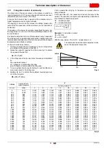
Page 12: ...e minimum output must not be lower than the minimum limit of the diagram RS 25 E BLU 45 kW RS 35 E BLU 72 kW Fig 1 D3831 mm A D E F 1 H I L O N V M RS 25 E BLU 442 422 508 230 365 140 305 138 780 84 1...

Page 13: ...it is necessary to reduce the output of the burner The reduction in output is accompanied by a reduction in the combustion chamber pressure Qr reduced output H1r reduced pressure Example 5 reduction...

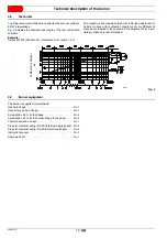
Page 14: ...combustion chambers of very different di mensions compared to those shown in the diagram of Fig 4 pre liminary checks are recommended 4 9 Burner equipment The burner is supplied complete with Gas tra...

Page 15: ...or TL versions 13 Filter to protect against radio disturbance 14 Flame inspection window 15 Ignition transformer 16 Socket for electrical wiring 17 Air servomotor 18 Air pressure switch differential t...

Page 16: ...harges must be avoided since they can damage the control box s electronic components when touched Installation notes Arrange the HV ignition cables separately as far as possible from the control box a...

Page 17: ...components in compliance with II and III ac cording to DIN EN 60730 1 Load on input terminals F1 unit fuse internal 6 3 AT Main fuse of perm network external Max 16 AT Undervoltage Safety switch off f...

Page 18: ...ly lines They should be sized for rated currents as per the pri mary external fuse and the fuse of the internal unit Min cross section Fuses used inside the control box F1 max 6 3 AT 0 75 mm 6 3 AT DI...

Page 19: ...VOMOTORS Air Fuel 90 Nominal load Post purging pos Ignition load Low flame Pos without load 0 S8870 Fig 7 Checking of seal Shutdown Operation Start up Timer Resolution Ratio Timer 1 parameters Timer 2...

Page 20: ...Ignition TA OFF Ph44 t44 interval time 1 Ph60 Operation Ph62 The burner moves to the switching off position Ph70 t13 post combustion time Ph72 The burner moves to the post purging position Ph74 t8 po...

Page 21: ...lockout Access to a lower level of the menu To navigate in Service or Info Mode and allows the selection of the parameter flashing symbol press for 1 s access to a lower level of the menu press from 1...

Page 22: ...or the fixing screws should be 1 5 Nm It is recommended that this value is not exceeded to prevent damaging the servomotor To avoid an excessive load on the bearings due to rigid hubs the use of compe...

Page 23: ...free from hazardous mixes e g chloride fluoride halo gen if present it is highly recommended to carry out cleaning and maintenance more frequently WARNING The handling operations for the burner can b...

Page 24: ...greater than the thickness of the boiler door com plete with its refractory The lengths L available are For boilers with front flue passes 13 Fig 17 a protection in re fractory material 11 must be in...

Page 25: ...ad and adjust them WARNING Before fixing the burner to the boiler check from the opening of the blast tube that the probe and the electrode are correctly positioned as in Fig 16 WARNING Do not rotate...

Page 26: ...e the 4 screws supplied with a tightening torque of 35 40 Nm after protecting their thread with anti seize products 5 8 Combustion head adjustment At this point of the installation the combustion head...

Page 27: ...p 5 9 Burner closing Once the combustion head adjustment is completed reassemble the burner on the guides 3 at about 100 mm from the pipe coupling 4 burner in the position shown in Fig 17 insert the p...

Page 28: ...k detection control is compulsory for burners with maximum outputs over 1200 kW 9 Gasket for flanged versions only 10 Pressure adjuster 11 Train burner adaptor supplied separately P2 Upstream pressure...

Page 29: ...ressure loss at gas butterfly valve 2 Fig 27 with maximum opening 90 To know the approximate output at which the burner is operating at its maximum Subtract the combustion chamber pressure from the ga...

Page 30: ...at the gas meter To know the required gas pressure at test point 1 Fig 27 set the maximum output required from the burner operation then find the nearest output value in the Tab K for the burner in qu...

Page 31: ...s is not the case a time switch should be fitted in series to TL to stop the burner at least once every 24 hours Refer to the wiring diagrams The electrical safety of the device is obtained only when...

Page 32: ...ith removable cover 4 5 pole socket for three phase power supply 5 2 pole socket for maximum gas pressure switch accessory 6 6A Fittings for pipe unions drill if 6A pipe unions are required 5 12 Calib...

Page 33: ...lding so you can notice the smell of gas Connect two lamps or testers to the two gas line solenoids to check the exact moment at which voltage is supplied This operation is unnecessary if each of the...

Page 34: ...be equal to or less than 150 kW with ts 3 s In order to measure the ignition output disconnect the plug socket 6 Fig 5 at page 13 on the ioni sation probe cable the burner will fire and then go into l...

Page 35: ...pressure switch connected in absolute mode Note the presence of a T connec tion not supplied In certain applications in strong depression situations the con nection of the pressure switch does not al...

Page 36: ...s phases of the start up ignition and switch off of the burner In the example the display indicates that the burner is in Phase 30 see diagram Fig 36 and there are 12s to the succes sive stage 6 6 1 3...

Page 37: ...is working in Manual mode any outside adjustment is excluded and only the safety devices are active Keep the F key pressed and with the keys or increase or decrease the load percentage To exit manual...

Page 38: ...med the list of parameters indicated on page 44 The factory set parameters are not visible To access this level you must follow Access procedure with password 6 6 4 1 Access procedure with password Pr...

Page 39: ...n derstood in seconds Press the key and increase the value to 25 seconds flash ing Press the key i reset to confirm and store To return to the list of parameters press the keys and ESC simultaneously...

Page 40: ...e value For the air servomotor keep the key A pressed the position in degrees flashes and press the keys or to increase or de crease the value To adjust the speed of the inverter expressed in and that...

Page 41: ...the section Procedure for inserting and adjusting points on the modulation curve at page 38 Phase 38 The ignition phase begins and the spark goes off Phase 40 The gas valves open the count of the saf...

Page 42: ...is is not the case work also on the gas valve stabiliser in this case however it is necessary to revise the calibrations of all the points previously set Once the calibration of point P1 is finished c...

Page 43: ...reset The parameter bAC_UP appears on the display screen confirm with the key i reset The display screen shows the following value Use the button The value will be set to 1 Value 1 is flashing confir...

Page 44: ...he parameter bAC_UP appears on the display screen With the key Select therEStorE parameter Confirm with the key i reset The display screen shows the following value Use the button The value will be se...

Page 45: ...is is to in dicate that the restore process has been completed correctly NOTE When the restore process is successfully completed the 0 value is shown on the display screen Err C information 136 D 1 re...

Page 46: ...Manual setting of output Not defined automatic operation 1 Modification zero setting 0 100 0 1 Not defined Info mode 123 Minimum output step position Index 0 BACS output Index 1 output of the externa...

Page 47: ...Reset 0 99999999 1 0 Info mode 200 CHECKS ON THE BURNER 201 Burner operation mode fuel supply line modulating stage servomotors etc not defined eliminate curves 1 Gmod 2 Gp1 mod 3 Gp2 mod 4 Lo mod 5 L...

Page 48: ...ication 0 3 1 2 Service mode 248 Gas Post purging time t3 at deactivation of the load LR ON 1 s Modification 1s 108 min 0 2s 1s Service mode 261 Oil selection of flame sensor 0 QRB QRC 1 ION QRA 1 Mod...

Page 49: ...ading only 0 255 1 0 Info mode Error chronology 701 725 05 Start up meter 25 Reading only 0 99999999 1 0 Info mode 725 Error chronology 701 725 06 Load 25 Reading only 0 100 0 1 0 Info mode 900 PROCES...

Page 50: ...Fig 39 at page 51 6 12 Burner flame goes out during operation If the flame accidentally goes out during operation the control box carries out a recycle i e it repeats the start up phase once and make...

Page 51: ...mini mum end of scale position Turn the air pressure switch to the maximum end of scale position The burner must stop in lockout Switch off the burner and disconnect the voltage Disconnect the minimu...

Page 52: ...rner Gas filter Replace the gas filter when it is dirty Boiler Clean the boiler as indicated in its accompanying instructions in order to maintain all the original combustion characteristics intact es...

Page 53: ...s are not normally required However if it is necessary to measure the ionisation current dis connect the plug socket on the ionisation probe cable and insert a direct current microammeter with a base...

Page 54: ...100 mm from the pipe coupling Reinsert the cables and slide the burner as far as the stop Connect the plug of the servomotor 14 Fig 17 at page 24 and tighten the grommet 15 Tighten the screws 5 Fig 4...

Page 55: ...ure on Lockout alarm at start 20 Air pressure fuel pressure on Alarm lock at start 68 Air pressure POC on Alarm lockout at start 84 Air pressure fuel pressure POC on Alarm lockout at start 4 Extraneou...

Page 56: ...iring Check if the closure contact of the valve opens when the valve is checked 64 POC Open Alarm lockout at the start software version V02 00 Check the wiring Check if the contact of the valve opens...

Page 57: ...ce point 1 Check if the servomotors have been inverted 2 Check if the servomotor is blocked or overloaded 1 Reference error of the air servomotor The reference of the air servomotor was not successful...

Page 58: ...not allowed If one of the 2 tests fails replace the control box because the contacts are definitively joined together and it is no longer possible to guarantee safety 98 Relay supervision error 2 Saf...

Page 59: ...last setting of the parameters If the error arises repeatedly replace the control box 132 EEPROM register initialisation internal error Perform a reset if the error arises repeatedly replace the cont...

Page 60: ...ng an adjustment of the curve via the PC interface the communication between REC 27 100A2 and the operating panel has been interrupted for more than 30 s 33 Manual lockout after the PC tool has perfor...

Page 61: ...ternal error Carry out a reset if the error arises repeatedly replace the control box 250 Internal error Carry out a reset if the error arises repeatedly replace the control box Error code Diagnostic...

Page 62: ...tial switch kit Maximum gas pressure switch Clean contacts kit A Appendix Accessories Burner Standard head length mm Extended head length mm Code RS 25 E BLU 230 365 3010430 RS 35 E BLU 230 365 301043...

Page 63: ...ration PVP kit Pressure Valve Proving Gas trains in compliance with EN 676 Please refer to manual Burner Code RS 25 35 E BLU 3010436 Burner Model Code RS 25 35 E BLU OCI412 3010437 Burner Blast tube l...

Page 64: ...layouts 2 Indication of references 3 REC27 operational layout 4 REC27 operational layout 5 REC27 operational layout 6 Electrical connections set by installer 7 Electrical connections for kit 8 Electri...

Page 65: ...63 20068118 GB Appendix Electrical panel layout RS 25 E BLU...

Page 66: ...20068118 64 GB Appendix Electrical panel layout RS 35 E BLU...

Page 67: ...65 20068118 GB Appendix Electrical panel layout RS 35 E BLU 3Ph...

Page 68: ...20068118 66 GB Appendix Electrical panel layout RS 25 35 E BLU...

Page 69: ...67 20068118 GB Appendix Electrical panel layout RS 35 E BLU 3Ph...

Page 70: ...20068118 68 GB Appendix Electrical panel layout...

Page 71: ...69 20068118 GB Appendix Electrical panel layout...

Page 72: ...20068118 70 GB Appendix Electrical panel layout...

Page 73: ...71 20068118 GB Appendix Electrical panel layout...

Page 74: ...ner arrest switch KM Fan motor contact maker MV Fan motor PA Air pressure switch PE Burner earth PGM Maximum gas pressure switch PGMin Minimum gas pressure switch PGVP Gas pressure switch for valve le...

Page 75: ......

Page 76: ...Subject to modifications RIELLO S p A I 37045 Legnago VR Tel 39 0442 630111 http www riello it http www riello com...

Reviews: