9
20159324
GB
Technical description of the burner
4.6
Maximum dimensions
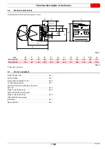
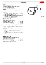
The dimensions of the burner are given in Fig. 1.
Tab. C
(1)
Blast tube: short-long
4.7
Burner equipment
Flange for gas train . . . . . . . . . . . . . . . . . . . . . . . . . . . . . . No. 1
Seal for flange . . . . . . . . . . . . . . . . . . . . . . . . . . . . . . . . . . No. 1
Flange fixing screws M 8 x 25 . . . . . . . . . . . . . . . . . . . . . . No. 4
Thermal flange gasket . . . . . . . . . . . . . . . . . . . . . . . . . . . . No. 1
Screws to fix the burner flange to the boiler:
M 8 x 25 . . . . . . . . . . . . . . . . . . . . . . . . . . . . . . . . . . . . . . . . No. 4
Plugs for electrical wiring . . . . . . . . . . . . . . . . . . . . . . . . . . No. 3
(RS 25-35/M C05 single-phase)
Plugs for electrical wiring . . . . . . . . . . . . . . . . . . . . . . . . . . No. 4
(RS 35/M C05 three-phase)
Instruction. . . . . . . . . . . . . . . . . . . . . . . . . . . . . . . . . . . . . . No. 1
Spare parts list . . . . . . . . . . . . . . . . . . . . . . . . . . . . . . . . . No. 1
mm
B
C
D
E
F
H
L
N
P
T
T (1)
U
RS 25/M C05
138
84
140
305
11/2”
422
442
177
508
230
365
780
RS 35/M C05
138
84
140
305
11/2”
422
442
177
508
198
333
780
Fig. 1
U
P
L
H
B
D
N
F
C
E
T ( 1 )
T
20147143


