25
20159324
GB
Start-up, calibration and operation of the burner
6.4
Burner ignition
Once the above steps are completed, the burner should ignite.
If the motor starts but the flame does not appear and the control
box goes into lockout, reset and wait for a new ignition attempt.
If ignition does not occur, it is possible that gas is not reaching the
combustion head within the safety time period of 3 seconds.
Therefore, it is necessary to increase gas ignition delivery.
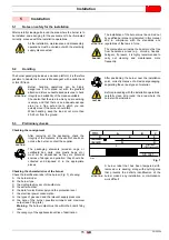
The arrival of gas to the sleeve is indicated by the U-type
pressure gauge (Fig. 25).
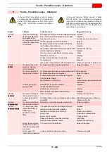
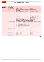
If the burner locks out again, refer to chapter "Faults - Possible
causes - Solutions” on page 35.
Once ignition has taken place, proceed with global calibration
operations.
6.5
Burner adjustment
The optimum adjustment of the burner requires an analysis of
flue gases at the boiler outlet.
Adjust successively:
Output upon ignition (minimum)
Max. burner output
Intermediate outputs between Min. and Max.
Air pressure switch
Minimum gas pressure switch
6.5.1
Determination of output upon ignition
(minimum)
According to the regulation EN 676.
Burners with MAX output up to 120kW
Ignition can be performed at the maximum operation output level.
Example:
•
max. operation output: 120 kW
•
max. ignition output: 120 kW
Burners with MAX output above 120kW
Ignition must be performed at a lower output than the max.
operation output.
If ignition output does not exceed 120 kW, no calculations are
required.
If ignition output exceeds 120 kW, the regulations prescribe that
the value be defined according to the control box safety time "ts":
for "ts" = 3s, ignition output must be equal to, or lower than, 1/3
of max. operation output.
Example:
MAX operation output of 450 kW.
The ignition output must be equal to, or less than,
150kW with ts = 3s
In order to measure the ignition output:
–
disconnect the plug-socket 24)(Fig. 4 on page 12) on the
ionisation probe cable (the burner will fire and then go into
lockout after the safety time has elapsed).
–
Perform 10 ignitions with consecutive lockouts.
–
Read, on the meter, the quantity of gas burned.
This quantity must be equal to, or lower than, the quantity
given by the formula, for ts = 3s:
Vg:
volume supplied in ignitions carried out (Sm
3
)
Qa:
ignition output (Sm
3
/h)
n:
number of ignitions (10)
ts
: safety time (sec)
Example
for gas G 20 (9.45 kWh/Sm
3
): ignition output 150 kW
corresponding to 15.87 Sm
3
/h.
After 10 ignitions with lockout, the output indicated on the meter
must be equal to, or less than:
6.5.2
Output upon ignition (minimum)
Min output must be selected within the firing rate range shown on
Fig. 2 on page 10.
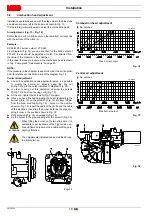
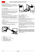
Press the button 2)(Fig. 26) “output reduction”, and keep it
pressed until the servomotor has closed the air damper and the
gas butterfly valve at 15° (adjustment made in the factory).
Adjusting gas delivery
Measure the gas delivery at the meter.
–
If it is necessary to reduce it, reduce slightly the angle of cam
III Fig. 28 on page 26
with small, regular movements, i.e.
bring it from an angle of 15° to 13° - 11°....
–
If it is necessary to increase it, press slightly the button
“output increase” 2)(Fig. 26) (open by 10-15° the gas butterfly
valve), increase the angle of cam III Fig. 28 on page 26 with
small, regular movements, i.e. bring it from an angle of 15° to
17° - 19°....
Then press the button “output reduction” until the servomotor
is in the position of minimum opening, and measure the gas
output.
Note
The servomotor follows the adjustment of cam III only when the
angle of the cam is reduced. If it is necessary to increase the
angle of the cam, you must first increase the angle of the
servomotor by means of the “output increase” key, then increase
the angle of cam III, and finally bring the servomotor to the
position of MIN output, with the “output reduction” key.
If it is necessary to adjust cam III Fig. 28, remove the cover
1)(Fig. 28) inserted with a trigger catch, as indicated in Fig. 28,
extract the special key 2)(Fig. 28) from inside, and insert it in the
notch of cam III.
ATTENTION
In the event the burner stops, in order to prevent
any damage to the installation, do not unblock the
burner more than twice in a row. If the burner
locks out for a third time, contact the customer
service.
DANGER
In the event there are further lockouts or faults
with the burner, the maintenance interventions
must only be carried out by qualified, authorised
personnel, in accordance with the contents of this
manual and in compliance with the standards and
regulations of current laws.
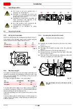
Vg =
3600
Qa
(max. burner output)
x n x ts
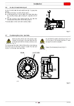
Vg =
3600
15.87 x 10 x 3
= 0.132 Sm
3

