background image

36

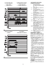
STATUS

Svolge tre funzioni:

1 - INDICA SUL VISORE V LE ORE DI FUN-

ZIONAMENTO ED IL NUMERO DI ACCEN-
SIONI DEL BRUCIATORE

Ore di funzionamento totali
Premere il pulsante "h1".
Ore di funzionamento in 2

°

 stadio

Premere il pulsante "h2".
Ore di funzionamento in 1

°

 stadio (calcolate)

Ore totali - ore in 2

°

 stadio.

Numero di accensioni
Premere il pulsante "count".
Azzeramento ore di funzionamento e n

°

 accen-

sioni
Premere contemporaneamente i tre pulsanti
"reset".
Memoria permanente
Le ore di funzionamento ed il n

°

 accensioni

rimangono in memoria anche nel caso di inter-
ruzione elettrica.

2 - INDICA I TEMPI DELLA FASE DI AVVIAMENTO

L'accensione dei led avviene con la seguente
successione, vedi Þg. A:

CON TERMOSTATO TR CHIUSO:
1 - Bruciatore spento, termostato TL aperto
2 - Chiusura termostato TL
3 - Avvio motore:

inizia il conteggio in sec. nel visore V

4 - Accensione bruciatore
5 - Passaggio in  2

°

 stadio

termina il conteggio in sec. nel visore V

6 - Dopo 10 sec. da 5 appare I I I I sul visore: 

la fase di avviamento • terminata.

CON TERMOSTATO TR APERTO:
1 - Bruciatore spento, termostato TL aperto
2 - Chiusura termostato TL
3 - Avvio motore:

inizia il conteggio in sec. nel visore V

4 - Accensione bruciatore
7 - Dopo 30 sec. da 4:

termina il conteggio in sec. nel visore V

8 - Dopo 10 sec. da 7 appare I I I I sul visore:

la fase di avviamento • terminata.

I tempi in secondi che appaiono sul visore V
segnalano la successione delle varie fasi di
avviamento indicate a pag. 32.

3 - IN CASO DI GUASTO DEL BRUCIATORE,

SEGNALA IL MOMENTO IN CUI QUESTO
E' AVVENUTO

Sono possibili 7 combinazioni di led accesi, vedi
Þg. (B).
Per le cause del guasto vedere i numeri tra
parentesi e, a pag. 38, il loro signiÞcato.
1  . . . . . . . . . . . (51)
2  . . . . . . . . . . . (10)
3  . . . . . . . . . . . (14 

¸

 19)

4  . . . . . . . . . . . (20 

¸

 38)

5  . . . . . . . . . . . (48 

¸

 50)

6  . . . . . . . . . . . (48 

¸

 50)

7  . . . . . . . . . . . (48 

¸

 50)

SigniÞcato dei simboli:

= Tensione presente

= Blocco motore vent. (non utilizzato)

= Blocco bruciatore (rosso)

= Funzionamento in 2

°

 stadio

= Funzionamento in 1

°

 stadio

= Carico raggiunto (Stand-by)

(A)

STATUS

LED lampeggiante
LED acceso
Tempo in secondi
La fase di avviamento • terminata

Led blinkend
Led erleuchtet
Zeit in Sekunden
Anfahrphase abgeschlossen

Led ßashing
Led illuminated
Time in seconds
Burner start cycle terminated

Led clignotante
Led allumŽe
Temps en secondes
La phase de dŽmarrage est terminŽe

Summary of Contents for RS 30 BLU

Page 1: ...ri di gas ad aria sof ata Gebl se Gasbrenner Forced draught gas burners Br leurs gaz air souf Funzionamento bistadio progressivo Zweistu g gleitender Progressive two stage operation Fonctionnement deu...

Page 2: ......

Page 3: ...Betriebsanleitung der Heizkessels ausgef hrt werden ein schlie lich Kontrolle der Konzentration von CO und CO2 in den Abgasen ihrer Temperatur und der mittlenen Kesseltemperatur D CONTENTS TECHNICAL...

Page 4: ...nsit assoluta kg Nm3 0 71 0 78 0 71 0 78 Portata massima Nm3 h 35 40 46 54 Pressione alla portata massima 2 mbar 13 3 19 7 13 8 20 4 FUNZIONAMENTO Intermittente min 1 arresto in 24 Bistadio alta e bas...

Page 5: ...40 46 54 Druck bei H chstdurchsatz 2 mbar 13 3 19 7 13 8 20 4 BETRIB Aussetzend min 1 Halt in 24 Std Zweistu g hohe und niedrige Flamme einstu g alles nichts STANDARDEINSATZ Heizkessel mit Wasser Dam...

Page 6: ...g Nm3 0 71 0 78 0 71 0 78 Max delivery Nm3 h 35 40 46 54 Pressure at maximunm delivery 2 mbar 13 3 19 7 13 8 20 4 OPERATION Intermittent min 1 stop in 24 hours Two stage high and low ame and single st...

Page 7: ...6 7 4 10 8 6 8 6 7 4 Densit absolute kg Nm3 0 71 0 78 0 71 0 78 D bit maximum Nm3 h 35 40 46 54 Pression au d bit max 2 mbar 13 3 19 7 13 8 20 4 FONCTIONNEMENT Intermittent 1 arr t min en 24 heures 2...

Page 8: ...sante di sblocco 21 Due interruttori elettrici uno per acceso spento bruciatore uno per 1 2 stadio 22 Spine per il collegamento elettrico 23 Serranda aria 24 Spina presa sul cavo della sonda di ionizz...

Page 9: ...button 21 Two switches one burner off on one for 1st 2nd stage operation 22 Plugs for electrical connections 23 Air gate valve 24 Plug socket on ionisation probe cable CONTROL BOX LOCK OUT if the con...

Page 10: ...lla camera di combustione di prova Esempio Potenza 350 Mcal h diametro 50 cm lunghezza 1 5 m CALDAIE COMMERCIALI C IMPOR TANTE L abbinamento bruciatore caldaia non pone pro blemi se la caldaia omologa...

Page 11: ...ations Figure B indicates the diameter and length of the test combustion chamber Example Output 350 Mcal h diameter 50 cm length 1 5 m COMMERCIAL BOILERS C IMPOR TANT The burner boiler combination doe...

Page 12: ...pressione 11 mbar colonna 1 corrisponde nella tabella RS 30 BLU una potenza in 2 sta dio di 310 kW Questo valore serve come prima approssima zione la portata effettiva va misurata al conta tore Per co...

Page 13: ...le RS 30 BLU 2nd stage operation Natural gas G 20 PCI 10 kWh Nm3 Gas ring 2 B p 16 adjusted as indicated in diagram C p 16 Gas pressure at test point 1 B 13 mbar Pressure in combustion chamber 2 mbar...

Page 14: ...are quindi la testa di combustione dal resto del bruciatore g B togliere la vite 13 ed estrarre il cofano 14 Sganciare lo snodo 4 dal settore graduato 5 Togliere le viti 2 dalle due guide 3 Togliere l...

Page 15: ...sensor probe and the ignition elec trode are correctly set in position as shown in C Now detach the combustion head from the burner g B remove screw 13 and withdraw the cover 14 Disengage the articula...

Page 16: ...la pressione indicata a pag 12 in 2 stadio e se la ghiera 2 B solo parzialmente aperta possibile aprire ulterior mente la ghiera di 1 2 tacche Continuando l esempio precedente a pag 12 si vede che per...

Page 17: ...air R2 2 gas R3 0 NOTE Diagram C show the ideal settings for the com bustion head If the gas mains pressure is too low to reach the 2nd stage operation pressure indicated on page 12 and if the ring 2...

Page 18: ...ne a valle del regolatore P3 Pressione a monte del ltro L1 Rampa gas fornita a parte con il codice indicato in tab C L1 A cura dell installatore LEGENDA TABELLA C C T Dispositivo controllo tenuta valv...

Page 19: ...10 Standard issue burner gasket with ange 11 Gas adjustment butter y valve 12 Burner 13 Gas valve 8 9 leak detection control device In accordance with EN 676 Standards gas valve leak detection contro...

Page 20: ...erruttore 1 2 stadio MV Motore ventilatore PA Pressostato aria SM Servomotore SO Sonda di ionizzazione SP Spina presa TA Trasformatore d accensione TB Terra bruciatore XP4 Presa a 4 poli XP6 Presa a 6...

Page 21: ...erference MMI 813 Control box I1 Switch burner off on I2 Switch 1st 2nd stage operation MV Fan motor PA Air pressure switch SM Servomotor SO Ionisation probe SP Plug socket TA Ignition transformer TB...

Page 22: ...X4 Spina a 4 poli X6 Spina a 6 poli X7 Spina a 7 poli PC Pressostato gas per controllo di tenuta PG Pressostato gas di min S Segnalazione di blocco a distanza S1 Segnalazione di blocco del controllo d...

Page 23: ...nd stage hourcounter IN Burner manual stop switch XP Plug for leak detection control device X4 4 pole plug X6 6 pole plug X7 7 pole plug PC Gas pressure switch for leak detection control device PG Min...

Page 24: ...A bruciatore funzionante in 2 stadio la farfalla del gas deve risultare tutta aperta 90 Camma St0 0 Limita la rotazione verso il minimo A bruciatore spento la serranda dell aria e la far falla del ga...

Page 25: ...ling the gas butter y valve The servomotor rotates through 90 degrees in 12 seconds Do not alter the factory setting for the 4 cams simply check that they are set as indicated below Cams St2 90 Limits...

Page 26: ...kW con ts 2 s 200 kW con ts 3 s Per misurare la potenza all accensione scollegare la spina presa 24 A p 8 sul cavo della sonda di ionizzazione il bruciatore si accende e va in blocco dopo il tempo di...

Page 27: ...rner will re and then go into lock out after the safety time has elapsed Perform 10 rings with consecutive lock outs On the meter read the quantity of gas burned This quantity must be equal to or lowe...

Page 28: ...no all interno dell apertura 6 A Possi bilmente non ruotare la prima vite quella che deve portare la serranda dell aria alla totale chiusura 4 POTENZE INTERMEDIE Regolazione del gas Non occorre alcuna...

Page 29: ...stage lock out will result In order to adjust cam St1 remove press t cover 1 as shown in g B extract the rele vant key 2 from inside and t it into the keyway in cam St1 Adjustment of air delivery Pro...

Page 30: ...re senza limite di riferimento per quanto riguarda il CO 6 PRESSOSTATO GAS DI MINIMA B Eseguire la regolazione del pressostato gas di minima dopo aver effettuato tutte le altre regola zioni del brucia...

Page 31: ...e le fonctionnement du ventilateur sans limit de r f rence pour le CO 6 PRESSOSTAT GAZ SEUIL MINIMUM B Effectuer le r glage du pressostat gaz seuil min apr s avoir effectu tous les autres r glages du...

Page 32: ...ldaia punto E L apparecchiatura elettrica continua comunque a controllare la presenza della amma e la cor retta posizione del pressostato aria Quando la temperatura o la pressione aumenta no all apert...

Page 33: ...i tor ame presence and the correct position of the air pressure switch When the temperature or the pressure increases until the control device TR opens the servomotor closes the gas butter y valve and...

Page 34: ...cinematismi che comandano la serranda aria e la farfalla del gas Cos pure bloccate devono essere le viti che ssano i cavi nella morsettiera del bruciatore Pulire esternamente il bruciatore particolar...

Page 35: ...me 4 A p 28 Br leur V ri er qu il n y ait pas d usure anormale ou de vis desserr e dans les m canismes qui com mandent le volet d air et la vanne papillon de gaz De m me les vis de xation des c bles a...

Page 36: ...ta CON TERMOSTATO TR APERTO 1 Bruciatore spento termostato TL aperto 2 Chiusura termostato TL 3 Avvio motore inizia il conteggio in sec nel visore V 4 Accensione bruciatore 7 Dopo 30 sec da 4 termina...

Page 37: ...g phase is terminated WITH REMOTE CONTROL THERMOSTAT TR OPEN 1 Burner off TL open 2 Control device TL closed 3 Motor start seconds count starts on read out V 4 Burner ring 7 30 seconds after stage 4 s...

Page 38: ...to da alta temperatura Sostituirlo e proteggerlo 27 Trasformatore d accensione difettoso Sostituirlo 28 Collegamenti elettrici valvole o trasformatore errati Controllarli 29 Apparecchiatura elettrica...

Page 39: ...ln und sch tzen 27 Defekter Z ndtrafo Auswechseln 28 Falsche Elektroanschl sse Ventile oder Trafo Kontrollieren 29 Defektes Steuerger t Auswechseln 30 Ein Ventil vor den Gasarmaturen geschlossen ffnen...

Page 40: ...deformed by high temperature Replace and protect 27 Ignition transformer defective Replace 28 Erroneous valve or transformer electrical connections Check 29 Control box defective Replace 30 A cock do...

Page 41: ...le prot ger 27 Transformateur d allumage d fectueux Le remplacer 28 Branchements lectriques vannes ou transformateur mal faits Les contr ler 29 Coffret de s curit d fectueux Le remplacer 30 Une vanne...

Page 42: ......

Page 43: ......

Page 44: ...R B L Riello Bruciatori Legnago s p a Via degli Alpini 1 I 37045 Legnago VR Tel 442 630111 Fax 442 21980 Con riserva di modi che nderungen vorbehalten Subject modi cations Sous r serve de modi cations...

Reviews: