background image

20037075

GB

Information and general instructions

1.2

Guarantee and responsibility

The manufacturer guarantees its new products from the installa-
tion date, in accordance with the regulations in force and/or the
sales contract. At the moment of the first start-up, check that the
burner is integral and complete.

In  particular,  the  rights  to  the  guarantee  and  the  responsibility
will no longer be valid, in the event of damage to things or injury
to people, if such damage/injury was due to any of the following
causes:

incorrect  installation,  start-up,  use  and  maintenance  of  the
burner;

improper, incorrect or unreasonable use of the burner;

intervention of unqualified personnel;

carrying out of non authorised modifications on the equipment;

use of the burner with safety devices that are faulty, incorrectly
applied and/or not working;

installation  of  untested  supplementary  components  on  the
burner;

powering of the burner with unsuitable fuels;

faults in the fuel power supply system;

use of the burner even following an error and/or an irregularity;

repairs and/or overhauls incorrectly carried out;

modification of the combustion chamber with inserts that pre-
vent  the  regular  development  of  the  flame,  as  structurally
established;

insufficient  and  inappropriate  surveillance  and  care  of  those
burner components most subject to wear and tear;

use  of  non-original  components,  including  spare  parts,  kits,
accessories and optionals;

force majeure.

the  manufacturer  furthermore  declines  any  and  every  re-
sponsibility  for  the  failure  to  observe  the  contents  of  this
manual.

1.2.1

Owner’s responsibility 

Please  pay  attention  to  the  Safety  Warnings  contained  within
this instruction manual. Keep this manual for your records and
provide it to your quali fi ed service agency for use in profession-
ally setting up and maintaining your burner.

Your burner will provide years of ef fi cient operation if it is pro-
fessionally installed and maintained by a qualifi ed service tech-
nician. If at any time the burner does not appear to be operating
properly, immediately contact your qualifi ed service agency for
consultation.

We  recommend  annual  inspection/service  of  your  gas  heating
system by a qualifi ed service agency. 

Failure to follow these instructions, misuse, or incorrect adjust-
ment of the burner could lead to equipment malfunction and re-
sult in asphyxiation, explosion or fire.

WARNING

Failure to observe the information given in this man-
ual, operating negligence, incorrect installation and
the carrying out of non authorised modifications will
result in the annulment by the manufacturer of the
guarantee that it supplies with the burner. 

WARNING

If you smell gas:

Do not touch any electrical items.

Open all windows.

Close all gas supply valves.

Contact your local gas authority immediately.

Do not store flammable or hazardous materials
in the vicinity of fuel burning appliances.

Improper  installation,  adjustment,  alteration,
service  or  maintenance  can  cause  property
damage, personal injury or death. 

Refer to this manual for instructional or addition-
al information. 

Consult a certified installer, service representa-
tive or the gas supplier for further assistance.

Burner  shall  be  installed  in  accordance  with
manufacturers requirements as outlined in this
manual,  local codes  and authorities having ju-
risdiction.

Summary of Contents for RS 300/EV FGR

Page 1: ...llation use and maintenance instructions Forced draught gas burners Progressive two stage or modulating operation CODE MODEL 20038037 RS 300 EV FGR RS 400 EV FGR 20036674 RS 500 EV FGR RS 650 EV FGR 2...

Page 2: ......

Page 3: ...air fuel ratio LMV52 17 3 11 Actuators 22 4 Installation 23 4 1 Notes on safety for the installation 23 4 2 Handling 23 4 3 Preliminary checks 23 4 4 Operation position 23 4 5 Boiler plate 24 4 6 Secu...

Page 4: ...itch 36 5 6 2 Maximum gas pressure switch 36 5 6 3 Minimum gas pressure switch 36 5 7 Final checks with the burner working 37 6 Maintenance 38 6 1 Notes on safety for the maintenance 38 6 2 Maintenanc...

Page 5: ...generator is to be installed The instruction manual shows the serial number of the burner the address and telephone number of the nearest Assis tance Centre The system supplier carefully informs the u...

Page 6: ...s manual 1 2 1 Owner s responsibility Please pay attention to the Safety Warnings contained within this instruction manual Keep this manual for your records and provide it to your quali fi ed service...

Page 7: ...th the burner components is not allowed apart from the parts requiring maintenance Only those parts envisaged by the manufacturer can be replaced 2 2 Personnel training The user is the person body or...

Page 8: ...740 5217 9468 19580 17800 min kW MBtu hr 555 1893 888 3030 1100 3787 Fuel max delivery pressure at max delivery 2 SCFH wc Natural gas 14070 7 Natural gas 16654 13 Natural gas 19138 15 Operation Low hi...

Page 9: ...Hz 120 1 60 Main power supply 10 V Ph Hz 230 3 60 460 3 60 575 3 60 Fan motor rpm V HP A 3500 230 12 4 28 3500 460 12 4 14 3500 575 12 4 11 2 Ignition transformer V1 V2 I1 I2 120 V 1 x 8 kV 1 6 A 20...

Page 10: ...tion W 23900 Electrical control circuit consumption W max 750 Total electrical consumption W 24650 Electrical protection NEMA 1 Model RS 800 EV FGR Control circuit power supply V Ph Hz 120 1 60 Main p...

Page 11: ...e safeguard RS 300 EV FGR 20038037 230 3 60 460 3 60 575 3 60 Inverter Burner mounted RS 400 EV FGR tbd 230 3 60 460 3 60 575 3 60 Inverter Burner mounted RS 500 EV FGR 20036674 230 3 60 460 3 60 575...

Page 12: ...37 34 9 64 RS 400 EV FGR 52 3 16 20 1 2 6 7 16 12 5 16 23 5 32 ANSI 3 ANSI 4 41 9 16 34 9 64 RS 500 EV FGR 52 3 16 20 1 2 6 7 16 14 17 32 23 5 32 ANSI 3 ANSI 6 46 7 8 34 9 64 RS 650 EV FGR 52 3 16 22...

Page 13: ...rs for movement of air damper 18 Air pressure switch 19 Air pressure test point 20 Maximum gas pressure switch with pressure test point 21 QRI infrared sensor 22 Hinge for opening burner 23 Air pressu...

Page 14: ...ith LCD display 22 Terminal strip XAUX 23 Bracket for shielded cables Warning used only to avoid a break in the cable s shielding hence do not overtighten 24 DIN bar for relay terminal strip XAUX and...

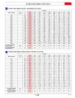
Page 15: ...30 RS 500 EV FGR 3787 RS 650 EV FGR 5415 RS 800 EV FGR 4535 Fig 5 0 2 4 6 8 10 12 14 16 18 mbar MBtu h 7 6 5 4 3 2 0 1 w c 0 5200 kW 4800 4400 4000 3600 3200 2800 2400 2000 1600 1200 800 400 0 2000 40...

Page 16: ...ir pressure 1 5 WC Real altitude 5000 ft Real temperature 108 F 108 F 68 F reference temp 40 F equivalent 2000 ft variation 40 2 20 x 100 2000 ft Proceeding as descripted above and considering a virtu...

Page 17: ...8 908 2 875 8 843 5 811 85 779 8 747 8 Average barometric pressure 68 F w c 399 394 385 371 358 345 332 320 307 294 CORRECTED BURNER AIR PRESSURE ACCORDING TO ALTITUDE Altitude Rated Pressure m a s l...

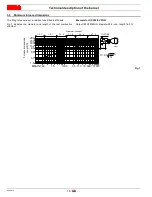
Page 18: ...ig 7 indicates the diameter and length of the test combustion chamber Example for RS 500 EV FGR Output 18500 MBtu hr diameter 39 4 inch length 16 5 ft 15 7 19 7 23 6 31 5 39 4 47 2 f t i nches ft 0 12...

Page 19: ...st also be observed Condensation and ingress of humidity must be avoided Should such conditions occur make sure that the unit will be completely dry before switching on again Static charges must be av...

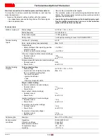
Page 20: ...se externally Max 16 AT Undervoltage Safety shutdown from operating position at mains voltage Restart on rise in mains voltage AC 96 V AC 100 V Oil pump magnetic clutch nominal voltage Nominal current...

Page 21: ...Fuel valve V1 Fuel valve V2 Fuel valve V1 Fuel valve V2 Fuel valve V3 Fuel valve SV Oil INPUTS Timer 1 Timer 2 Fuel 1 oil Fuel 2 gas Controller ON internal external Air pressure switch LP Start relea...

Page 22: ...1 t78 Postpurge time 3 gas oil tn3 t80 Valve proving evacuate time t81 Leakage test time atmospheric pressure t82 Leakage test filling test t83 Leakage test time gas pressure tmn1 Min time extraneous...

Page 23: ...Output is active when fan is on and for another 15 s after fan is switched off 17 Parameter Start pressure switch valve PS_Re li_Inv Output pressure switch valve will be logically inverted 18 Paramete...

Page 24: ...30 V section of the actuator is strictly segregat ed from the functional low voltage section The holding torque is reduced when the actuator s power supply is switched off Technical data WARNING To av...

Page 25: ...e WARNING The handling operations for the burner can be high ly dangerous if not carried out with the greatest at tention keep any unauthorised people at a distance check the integrity and suitablenes...

Page 26: ...ler manufacturer 4 6 2 Burner securing Create a suitable hoisting system by hooking onto the rings 3 Fig 13 removing the fastening screws 7 securing the cover 8 first Slip the thermal protection onto...

Page 27: ...is pre arranged in the plant for the maximum run hole 3 Fig 16 When dealing with boilers featuring a strong back pressure if air delivery is insufficient even with the damper fully open you can use a...

Page 28: ...nd remove the 6 nozzles 3 Re assemble with reverse procedure re placing all the burner components as originally Fig 18 4 2 1 0 4545 6060 7575 9090 10605 12120 13635 15150 16664 3 2 1 0 9090 10605 1212...

Page 29: ...sate drip legs and catch space volume of drip legs to prevent the condensation from flowing through the control valves and into the fan In cases of heavy condensation a condensate drip leg may be requ...

Page 30: ...ff 3 x 15 45 to account for bends We then obtain a maximum pipe value of 55 You understand that pipe diameter is too small so we must choose a 8 diameter Maximum allowed pipe length FGR 250 3 x 15 205...

Page 31: ...type approved according to required standards and is supplied separately from the burner Fig 22 Key Fig 22 1 Gas input pipe for main burner 2 Manual valve 3 Min gas pressure switch 4 Safety shut off v...

Page 32: ...ample for RS 500 EV FGR Maximum output operation Gas pressure at test point 1 Fig 23 11 7 WC Pressure in combustion chamber 2 WC 11 7 2 9 7 WC An output of 15148 MBtu hr shown in Tab I corresponds to...

Page 33: ...those shown in the electri cal layouts Check that the electrical supply of the burner corresponds to that shown on the identification label and in this manual Do not invert the neutral with the phase...

Page 34: ...be done as shown in Fig 26 3 Possible pressure temperature probes and O2 sensor con nection must be done as shown in Fig 26 4 12 Speed sensor adjustment WARNING It is very important to shield the mot...

Page 35: ...lamping the cable to the earth plate The screen must be earthed on both side of the cable take care for good earthing system Examples Number 1 2 3 show not proper ways to earth a cable screen WARNING...

Page 36: ...ted on page 25 In addition the following adjustments must also be made open manual valves up stream from the gas train Purge the air from the gas line Adjust the min gas pressure switch Fig 36 to the...

Page 37: ...unctions ensuring top level en ergy and operational performance from the burner both for single and grouped burners e g boiler with a double combustion cham ber or several generators in parallel The s...

Page 38: ...ore To check this insert a combustion analyser into the chimney slowly close the fan suction inlet for example with cardboard and check that the burner locks out before the CO in the fumes exceeds 1 5...

Page 39: ...he maximum end of scale position Rotate the maximum oil pressure switch at the minimum of the scale The burner must stop in lockout Switch off the burner and disconnect the voltage Disconnect the mini...

Page 40: ...wer it can depend on photocell positioned incorrectly low corrent lower than 96V bad regulation of the burner To measure power use a voltometer with a 10 Vdc scale connect ed as illustrated in Fig 37...

Page 41: ...s 5 At this point it is possible to open the burner at the hinge 6 4 Closing the burner Close the burner at the hinge and apply screw 5 connect the gas pressure switch test point 4 Connect the gas ser...

Page 42: ...S 300 400 500 RS 800 RS 650 8 12 13 14 20 19 16 15 8 23 24 24 28 27 29 30 31 54 51 25 50 36 35 34 33 37 39 38 40 41 42 43 44 45 46 47 46 48 49 11 19 18 21 26 22 1 1 1 5 6 7 4 2 3 7 6 4 5 2 3 2 5 4 3 6...

Page 43: ...014118 ELBOW 7 3014117 CONTROL WHEEL 7 3014116 CONTROL WHEEL 8 3013253 SERVOMOTOR 11 20042596 AIR INTAKE ASSEMBLY 11 20042619 AIR INTAKE ASSEMBLY 11 20042675 AIR INTAKE ASSEMBLY 12 20006205 FAN 12 301...

Page 44: ...117 FLANGE GASKET 32 3013956 FLANGE GASKET 33 3012956 TRANSFORMER 34 20031413 HORN 35 3012948 AIR PRESSURE SWITCH 35 20014075 AIR PRESSURE SWITCH 35 20013975 AIR PRESSURE SWITCH 36 3013363 CONNECTOR 3...

Page 45: ...ttings 52 20014102 ELECTRODE CONNECTION 53 3007170 O RING 54 3013327 EXTERNAL TIE ROD 55 3013324 INTERNAL TIE ROD 56 3013330 AIR DIFFUSER 56 20011119 AIR DIFFUSER 56 3013955 AIR DIFFUSER 57 3014121 DI...

Page 46: ...B Appendix Accessories Gas train according to UL Standards B Appendix Accessories WARNING The installer is responsible for the supply and instal lation of any required safety device s not indicated in...

Page 47: ...2 Low Fire High Fire Main Power Supply O2 Low Fire High Fire Control Power Supply CO Low Fire High Fire Burner Firing Rate NOX Low Fire High Fire Manifold Pressure Net Stack Temp Low Fire High Fire Pi...

Page 48: ...ICA 35 Pond Park Road 1 800 4 RIELLO 2165 Meadowpine Blvd Hingham Massachusetts 1 800 474 3556 Mississauga Ontario U S A 02043 Canada L5N 6H6 http www riello ca RIELLO S p A I 37045 Legnago VR Tel 39...

Reviews: