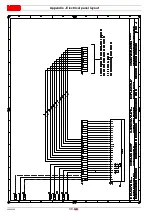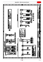
20098208
24
GB
Start-up, calibration and operation of the burner
6.7.2
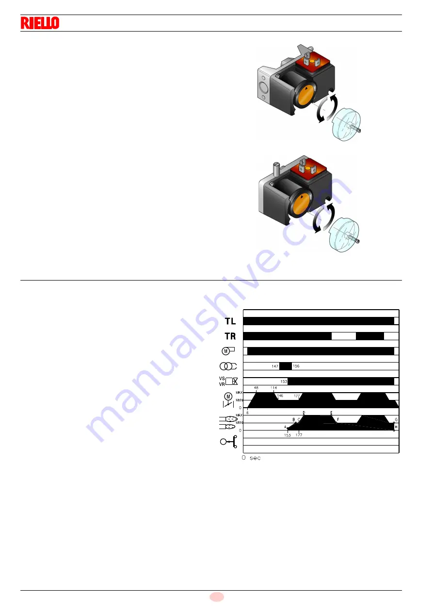
Maximum gas pressure switch
Adjust the maximum gas pressure switch (Fig. 31) after perform-
ing all other burner adjustments with the maximum gas pressure
switch set to the end of the scale.
With the burner operating at maximum output, lower adjustment
pressure by slowly turning the relative knob anticlockwise until
the burner locks out.
Turn the knob clockwise by 2 mbar and repeat the start-up of the
burner.
If the burner locks out again, turn the knob clockwise again by 1
mbar.
6.7.3
Minimum gas pressure switch
Adjust the minimum gas pressure switch (Fig. 32) after perform-
ing all the other burner adjustments with the pressure switch set
to the start of the scale.
With the burner operating at maximum output, increase adjust-
ment pressure by slowly turning the relative knob clockwise until
the burner locks out.
Then turn the knob anticlockwise by 2 mbar and repeat burner
start-up to ensure it is uniform.
If the burner locks out again, turn the knob anticlockwise again by
1 mbar.
6.8
Operation sequence of the burner
6.8.1
Burner start-up
0s
TL thermostat/pressure switch closes.
6s
Fan motor starts up. Servomotor starts: 130 rotation to
the right, until contact is made on cam I.
48s
The air damper is positioned to MAX output.
48s
Pre-purging stage with MAX output air delivery.
Duration 66 seconds.
144s
The servomotor rotates to the left up to the angle set on
the cam II.
146s
The air damper and the gas butterfly valve adopt the MIN
output position (with cam II).
147s
Ignition electrode strikes a spark.
164s
The safety valve VS opens, along with the adjustment
valve VR (quick opening).
The flame is ignited at a low output level, point A
(Fig. 33). Output is then progressively increased, with the
valve opening slowly up to MIN output, point B (Fig. 33).
156s
The spark goes out.
177s
The control box start-up cycle ends.
Fig. 31
D3856
Fig. 32
D3855
Fig. 33
NORMAL IGNITION
20061660


