20098208
26
GB
Maintenance
7.1
Notes on safety for the maintenance
The periodic maintenance is essential for the good operation,
safety, yield and duration of the burner.
It allows you to reduce consumption and polluting emissions and
to keep the product in a reliable state over time.
Before carrying out any maintenance, cleaning or checking oper-
ations:
7.2
Maintenance programme
7.2.1
Maintenance frequency
7.2.2
Checking and cleaning
Combustion
Carry out an analysis of the combustion discharge gases.
Significant differences with respect to the previous check indicate
the points where more care should be exercised during mainte-
nance.
Combustion head
Open the burner and make sure that all components of the
combustion head are in good condition, not deformed by the
high temperatures, free of impurities from the surroundings
and correctly positioned.
Burner
Check that there are not excess wear or loosen screws.
Clean the outside of the burner.
Fan
Check to make sure that no dust has accumulated inside the fan
or on its blades, as this condition will cause a reduction in the air
flow rate and provoke polluting combustion.
Boiler
Clean the boiler as indicated in its accompanying instructions in
order to maintain all the original combustion characteristics in-
tact, especially the flue gas temperature and combustion cham-
ber pressure.
Flame presence check
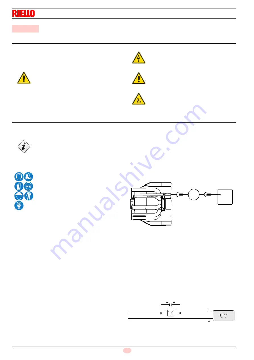
The burner is fitted with an ionisation system to check that a
flame is present. The minimum current for control box operation
is 6 µA (Fig. 35).
The burner provides a much higher current, so controls are not
normally required. However, if it is necessary to measure the ion-
isation current, disconnect the plug-socket on the ionisation
probe cable and insert a direct current microammeter with a base
scale of 100 µA. Carefully check the polarities!
Electrical current to UV cell
Clean the glass cover from any dust that may have accumulated.
To remove the photocell, pull out outwards; it is only pressed in.
Minimum value for correct operation: 70 µA.
If the value is lower, it could be due to:
–
exhausted photocell
–
low voltage (lower than 187 V)
–
bad regulation of the burner
In order to measure the current, use a microammeter of 100 mA
c.c., connected in series to the photocell, as in the scheme, with
a capacitor of 100 mF - 1V c.c. at the same level of the instru-
ment.
7
Maintenance
DANGER
The maintenance interventions and the calibration
of the burner must only be carried out by qualified,
authorised personnel, in accordance with the con-
tents of this manual and in compliance with the
standards and regulations of current laws.
DANGER
Disconnect the electrical supply from the burner
by means of the main system switch.
DANGER
Close the fuel interception tap.
Wait for the components in contact with heat
sources to cool down completely.
The gas combustion system should be checked at
least once a year by a representative of the man-
ufacturer or another specialised technician.
The operator must use the required equipment
during maintenance.
Fig. 35
-
+
µ
A
D3097
Fig. 36
D1143


