21
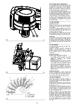
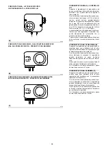
ELEKTRODEN (A)
Kontrollieren Sie, ob Sonde und Elektrode wie in
Abb. (A) ausgerichtet sind.
EINSTELLUNG DES FLAMMKOPF (B)
Über der Veränderung der Luftmenge je nach Lei-
stungsbedarf hinaus, verändert der Stellantrieb
4)(A)Seite 12 durch ein Hebelsystem die Einstel-
lung des Flammkopfs.
Mit diesem System ist auch bei minimalem
Regelbereich eine optimale Einstellung möglich.
Bei gleicher Drehung des Stellantriebs kann die
Öffnung des Flammkopfs durch Verschiebung
der Zugstange in die Löcher 1-2-3 variiert wer-
den, Abb. (B).
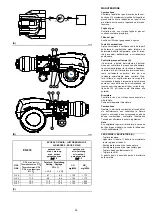
Das zu verwendende Loch (1-2-3) wird nach
Diagramm (D) auf der Grundlage der geforder-
ten Höchstleistung gewählt.
Werkseitig wird die Einstellung für den Höchst-
hub (Loch 3) vorbereitet.
Solte der Luftdurchsatz an Heizkesseln mit star-
kem Gegendruck auch bei ganz geöffneter Luft-
klappe nicht ausreichend sein, so kann eine
andere Einstellung als die im Diagramm (D)
angegebene ausgeführt werden, wobei die Zug-
stange in das nächste Loch mit der höheren
Zahl zu verschieben ist, was die Öffnung des
Flammkopfs und daher den Luftdurchsatz ver-
größert.
Für den Betrieb an Heizkesseln mit
Flammenumkehr müssen die Gas-
rohre im Loch auf Position 4 regu-
liert sein – siehe Abb. (E).
DREHUNG DES GEBLÄSEMOTORS
Vor dem Lüfterrad zur Kühlung des Gebläsemo-
tors stehen und prüfen, dass sich dieses gegen
den Uhrzeigersinn dreht.
POSITION OF ELECTRODES (A)
Make sure that the electrode and the probe are
positioned as shown in figure (A).
COMBUSTION HEAD SETTING (B)
In addition to varying air flow depending on the
output requested, the servomotor 4)(A) pag. 12 -
by means of a lifting assembly - varies the set-
ting of the combustion head.
This system allows an optimal setting even at a
minimum firing rate.
For the same servomotor rotation, combustion
head opening can be varied by moving the tie
rod onto holes 1-2-3, fig. (B).
The choice of the hole (1-2-3) to be used is de-
cided on the basis of diagram (D) against the re-
quired maximum output.
Setting is pre-arranged in the plant for the maxi-
mum run (hole 3).
When dealing with boilers featuring a strong
back pressure, if air delivery is insufficient even
with the damper fully open, you can use a differ-
ent setting to that illustrated in diagram (D) - do
this by moving the tie rod onto the next highest
hole numerically speaking, thus increasing the
combustion head»s opening and hence air deliv-
ery.
For operation on flame-reversal
boilers, gas pipes must be adjusted
to hole position 4, see Fig. (E).
ROTATION OF FAN MOTOR
Look at the fan motor's cooling fan from the front
and make sure it turns anticlockwise.
POSITION DES ELECTRODES (A)
Contrôler si les électrodes sont positionnées
comme sur la fig. (A).
RÉGLAGE TÊTE DE COMBUSTION (B)
A l»aide d»un levier de transmission, le servomo-
teur 4)(A) page 12 varie le débit d»air en fonction
de la demande de puissance et du réglage de la
tête de combustion.
Ce système permet un réglage optimal même
pour une plage de puissance minimum.
Il est possible de modifier l»ouverture de la tête
de combustion, tout en ayant la même rotation
du servomoteur, en déplaçant le tirant sur les
trous 1, 2 et 3 (fig. B).
Le trou à utiliser (1-2-3) est choisi selon le dia-
gramme (D) sur la base de la puissance maxi-
mum demandée.
Le réglage en usine est prévu pour une course
maximum (trou 3).
Si le débit d»air est insuffisant, par exemple dans
les chaudières où il y a une forte contre-pres-
sion, même quand le volet d»air est entièrement
ouvert, il est possible de faire un réglage autre
que celui indiqué sur le diagramme (D) en met-
tant le tirant sur le trou dont le numéro est plus
grand, ce qui augmente l»ouverture de la tête de
combustion et donc le débit d»air.
Pour le fonctionnement sur les
chaudières à inversion de flamme,
les tuyaux du gaz doivent être
réglés sur le trou 4, voir Fig. (E).
ROTATION MOTEUR VENTILATEUR
Se placer face à l»hélice de refroidissement du
moteur du ventilateur et vérifier si elle tourne
dans le sens inverse aux aiguilles d»une montre.


