background image

40

Appendice - Anhang - Appendix - Annexe

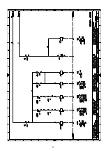
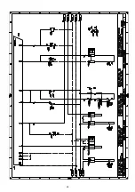
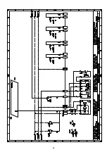
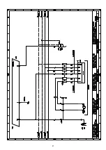
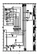
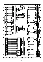
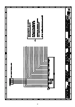
Schema quadro elettrico - Schaltplan
Layout of electric panel board - Schéma tableau électrique

2

Indicazione riferimenti - Bezugangabe - References layout - Indication références

N. foglio - Seite - Page

/1.A1

Coordinate - Koordinaten - Coordinates - Coordonnées

1

2

Indicazione riferimenti - Bezugangabe

Schema funzionale avviatore stella/triangolo - Betriebsschema des Stern/Dreieckanlasser

4

5

6

INDICE - INHALT - CONTENTS - INDEX

References layout - Indication références

Star/delta starter operational diagram - Schéma fonctionnel demarreur etoile/triangle

Schema funzionale RMG/M... - Betriebsschema RMG/M...

RMG/M... operational layout - Schéma fonctionnel RMG/M...

Schema funzionale rampa gas - Betriebsschema der Gasarmaturen

Gas train operational layout - Schéma fuonctionnel rampe gaz

7

Schema funzionale RMG/M... - Betriebsschema RMG/M...
RMG/M... operational layout - Schéma fonctionnel RMG/M...

8

Schema funzionale RMG/M... - Betriebsschema RMG/M...
RMG/M... operational layout - Schéma fonctionnel RMG/M...

Collegamenti elettrici kit RWF40 interno - Elektroanschlüsse interner Kit RWF40
Electrical connections for internal RWF40 kit - Raccordements électrique kit RWF 40 intérieur

10

Collegamenti elettrici a cura dell»installatore - Elektroanschlusse vom Installateur auszuführen
Electrical connections set by installer - Raccordements électrique par l»installateur

11

Schema funzionale RWF40... - Betriebsschema RWF40...
RWF40... operational layout - Schéma fonctionnel RWF40...

12

Collegamenti elettrici kit RWF40 esterno - Elektroanschlüsse externer Kit RWF40
Electrical connections for external RWF40 kit - Raccordements électrique kit RWF 40 extérieur

3

Schema unifilare di potenza - Eindrahtiges Leistungsschema
Layout of unifilar output - Schéma unifilaire de puissance

9

Summary of Contents for RS 300/M BLU

Page 1: ...ructions Manuel d entretien Bruciatori di gas Gasbrenner Gas burners Br leurs gaz Funzionamento modulante Modulierender Betrieb Modulating operation Fonctionnement modulant 2916154 1 CODICE CODE MODEL...

Page 2: ......

Page 3: ...33 St rungen Abhilfen 35 Normalbetrieb Flammenf hlzeit 38 Anhang Schaltplan 40 D CONTENTS Technical data page 8 Accessories 8 List of available models 9 Burner description 13 Description of panel boar...

Page 4: ...NTE C max 60 ALIMENTAZIONE ELETTRICA 3N 400 230V 10 50 Hz MOTORE VENTILATORE avviamento stella triangolo per RS400 e RS500 rpm V kW A 2900 230 400 4 5 15 8 9 1 2900 400 680 7 5 16 9 2900 400 680 9 2 1...

Page 5: ...unzionamento continuo 1 stop ogni 72 h Alimentazione elettrica del sistema 3 400 50 3 230 50 Tensione ausiliari 230 50 60 R S 500 M TC Emissione Classe 1 EN267 EN676 MZ Classe 2 EN267 EN676 BLU Classe...

Page 6: ...NGSLUFT C max 60 ELEKTRISCHE SPEISUNG 3N 400 230V 10 50 Hz GEBL SEMOTOR Stern Dreieck Schaltung bei RS400 und RS500 rpm V kW A 2900 230 400 4 5 15 8 9 1 2900 400 680 7 5 16 9 2900 400 680 9 2 18 10 5...

Page 7: ...1 Abschaltung in 24 Std Dauerbetrieb 1 Abschaltung in 72 Std Stromversorgung des Systems 3 400 50 3 230 50 Spannung der Hilfskreise 230 50 60 R S 500 P TC Emission Klasse 1 EN267 EN676 MZ Klasse 2 EN2...

Page 8: ...max 60 ELECTRICAL SUPPLY 3N 400 230V 10 50 Hz FAN MOTOR star delta starting for RS400 and RS500 rpm V kW A 2900 230 400 4 5 15 8 9 1 2900 400 680 7 5 16 9 2900 400 680 9 2 18 10 5 IGNITION TRANSFORMER...

Page 9: ...rking 1 stop every 72 h Electrical supply to the system 3 400 50 3 230 50 Auxiliary voltage 230 50 60 R S 500 M TC Emission Class 1 EN267 EN676 MZ Class 2 EN267 EN676 BLU Class 3 EN267 EN676 MX Class...

Page 10: ...RANT C max 60 ALIMENTATION ELECTRIQUES 3N 400 230V 10 50 Hz MOTEUR VENTILATEUR d marrage toile triangle pour RS400 et RS500 rpm V kW A 2900 230 400 4 5 15 8 9 1 2900 400 680 7 5 16 9 2900 400 680 9 2...

Page 11: ...eures Fonctionnement continuos 1 arr t min en 72 heures Alimentation lectrique du syst me 3 400 50 3 230 50 Tension auxiliaires 230 50 60 R S 500 M TC mission Classe 1 EN267 EN676 MZ Classe 2 EN267 EN...

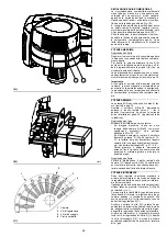
Page 12: ...uliti 3 Trasformatore d accensione 4 Staffa per l applicazione del kit Regolatore di potenza RWF40 5 Pulsante di stop 6 Selettore spento automatico manuale 7 Selettore aumento diminuzione potenza 8 Se...

Page 13: ...Terminal strip for kits 2 Relay outlet clean contacts 3 Ignition transformer 4 Bracket for mounting the power regulator RWF40 5 Stop push button 6 Dial for off automatic manual 7 Power dial for increa...

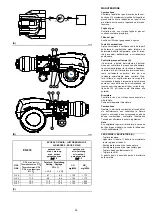
Page 14: ...Istruzione 1 Catalogo ricambi INGOMBRO B misure indicative L ingombro del bruciatore riportato in fig B Tener presente che per ispezionare la testa di combustione il bruciatore deve essere aperto ruot...

Page 15: ...UIPMENT 1 Flange gasket 8 Flange fixing screws M 16 x 50 1 Thermal insulation screen 4 Screws to secure the burner flange to the boiler M 18 x 70 1 Instruction booklet 1 Spare parts list MAX DIMENSION...

Page 16: ...e la caldaia omologata CE e le dimensioni della sua camera di combustione sono vicine a quelle indicate dal diagramma B Se invece il bruciatore deve essere applicato ad una caldaia non omologata CE e...

Page 17: ...ler matching does not pose any problems if the boiler is CE type approved and its combustion chamber dimensions are similar to those indicated in diagram B If the burner must be combined with a boiler...

Page 18: ...DEL BRUCIATORE ALLA CALDAIA B Predisporre un adeguato sistema di solleva mento agganciandosi agli anelli 3 B Infilare la protezione termica data a corredo sul boccaglio 4 B Infilare tutto il bruciator...

Page 19: ...essly requested by the boiler manufac turer SECURING THE BURNER TO THE BOILER B Prepare an adequate system of hoisting by hooking onto the rings 3 B Slip the thermal protection standard equip ment ont...

Page 20: ...por tata d aria sia insufficiente possibile eseguire una taratura diversa da quella indicata dal dia gramma D spostando il tirante sul foro suc cessivo numericamente pi alto aumentando cos l apertura...

Page 21: ...e cided on the basis of diagram D against the re quired maximum output Setting is pre arranged in the plant for the maxi mum run hole 3 When dealing with boilers featuring a strong back pressure if ai...

Page 22: ...GASARMATUREN GAS TRAINS APPROVED ACCORDING TO EN 676 RAMPES GAZ HOMOLOGU ES SELON LA NORME EN 676 Gas trains 9 11 type A 11 type B Type Code Code Code L3 Code L3 MBC 1200 SE 50 2 3970221 3010344 3000...

Page 23: ...6 Standards gas valve leak detection control devices are compulsory for burners with maximum outputs of more than 1200 kW 10 Adjustment solenoid VR vertical Two adjustments ignition delivery rapid ope...

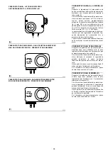
Page 24: ...Compie una rotazione di 130 in 43 s Non modificare la regolazione fatta in fabbrica alle 4 camme di cui dotato solo controllare che esse siano come sotto riportato Camma 1 blu 0 Limita la rotazione v...

Page 25: ...TOR B The servomotor provides simultaneous adjust ment of the air gate valve by means of the vari able profile cam and the gas butterfly valve It rotates through 130 degrees in 43 seconds Do not alter...

Page 26: ...ia e la farfalla del gas a 35 regolazione fatta in fabbrica Regolazione del gas Misurare la portata del gas al contatore Se bisogna diminuirla ridurre un poco l angolo della camma 2 B p 24 con piccoli...

Page 27: ...duced decrease the angle of cam 2 B p 24 slightly by proceeding a little at a time until the angle is changed from 35 to 33 31 If it has to be increased turn the increase output selector 2 D p 24 i e...

Page 28: ...a B Con il bruciatore funzionante alla potenza mas sima diminuire la pressione di regolazione girando lentamente in senso antiorario l apposita manopolina fino al blocco del brucia tore Girare quindi...

Page 29: ...witch after having performed all the other burner adjust ments with the pressure switch set at the end of the scale B With the burner operating at maximum output decrease adjustment pressure by slowly...

Page 30: ...tinua da 100 A fondo scala Attenzione alla polarit Bruciatore Controllare che non vi siano usure anomale o viti allentate Pulire esternamente il bruciatore Combustione Qualora i valori della combusti...

Page 31: ...ure the ionisation current disconnect the plug socket on the ionisation probe cable and insert a direct current microam perometer with a base scale of 100 A Care fully check polarities Burner Check fo...

Page 32: ...aria Se la temperatura o la pressione bassa per cui il TR chiuso il bruciatore aumenta pro gressivamente la potenza fino al valore MAX tratto C D Se poi la temperatura o la pressione aumenta fino all...

Page 33: ...sure is low and the TR is consequently closed the burner pro gressively increases its output to the MAX value section C D If subsequently the temperature or pressure increases until TR opens the burne...

Page 34: ...bruciatore si avvia ma si arresta in blocco 17 Presenza di fiamma durante la preventilazione Verificare tenuta valvola 18 Guasto all apparecchiatura elettrica Sostituire apparecchiatura 7 lampeggi Il...

Page 35: ...ber in St rab schaltung an 17 Flamme bei Vorbel ftung vorhanden Dichtheit des Ventils berpr fen 18 Defekt am Steuerger t Ger t austauschen 7 maliges Blinken Der Brenner geht gleich nach der Flam menbi...

Page 36: ...djust it or replace it 5 flashes The burner starts up but halts in lock out 17 Flame presence during pre purging Check the valve tightness 18 Fault on electric control box Replace control box 7 flashe...

Page 37: ...r sence de flamme durant la pr ventilation Contr ler l tanch it de la vanne 18 Panne de la bo te lectrique Remplacer la bo te lectrique 7 clignotements Le br leur se bloque juste apr s l appari tion d...

Page 38: ...nden Abbildung gezeigt Die Impulse der LED verursachen ein Signal das ca alle 3 Sekunden gegeben wird Die Anzahl der Impulse wird die Zeit festlegen die der F hler ab ffnung der Gasventile f r die Wah...

Page 39: ...e Les impulsions du LED constituent un signal espac d environ 3 secondes Le nombre d impulsions indique le TEMPS DE R V LATION de la sonde d s l ouverture des vannes gaz comme d apr s le tableau suiva...

Page 40: ...uonctionnel rampe gaz 7 Schema funzionale RMG M Betriebsschema RMG M RMG M operational layout Sch ma fonctionnel RMG M 8 Schema funzionale RMG M Betriebsschema RMG M RMG M operational layout Sch ma fo...

Page 41: ...41...

Page 42: ...42...

Page 43: ...43...

Page 44: ...44...

Page 45: ...45...

Page 46: ...46...

Page 47: ...47...

Page 48: ...48...

Page 49: ...49...

Page 50: ...50...

Page 51: ...51...

Page 52: ...52...

Page 53: ...o S p a declina ogni responsabilit da modifiche o collega menti diversi da quelli rappresentati in questi schemi ZEICHENERKL RUNG SCHEMEN A1 Steuerger t B1 Interner Leistungsregler RWF40 B2 Externer L...

Page 54: ...dia grams L GENDE SCH MAS ELECTRIQUE A1 Coffret de s curit B1 R gulateur de puissance RWF40 int rieur B2 R gulateur de puissance RWF40 ext rieur BA Entr e avec courant DC 0 20 mA 4 20 mA BA1 Entr e a...

Page 55: ......

Page 56: ...RIELLO S p A I 37048 Legnago VR Tel 39 0442 630111 www rielloburners com Con riserva di modifiche nderungen vorbehalten Subject modifications Sous r serve de modifications...

Reviews: