background image

37

WARTUNG

Verbrennung
Die  Abgase  der  Verbrennung  analysieren.
Bemerkenswerte  Abweichungen  im  Vergleich
zur  vorherigen  Überprüfung  zeigen  die  Stelle
an,  wo  die  Wartung  aufmerksamer  ausgeführt
werden soll.

Gasundichtigkeiten
Die  Zähler-Brenner-Leitung  auf  Gasundichtig-
keiten kontrollieren.

Gasfilter
Verschmutzten Gasfilter austauschen.

Flammkopf
Den  Brenner  öffnen  und  überprüfen,  ob  alle
Flammkopfteile  unversehrt,  nicht  durch  hohe
Temperatur verformt, ohne Schmutzteile aus der
Umgebung und richtig positioniert sind.

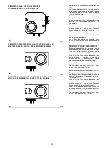
FLAMMENÜBERWACHUNG (A)
Der  Brenner  ist  mit  einem  Ionisationsgerät  zur
Flammenüberwachung  ausgerüstet.  Der  erfor-
derliche  Mindeststrom  beträgt  6  µA.  Da  der
Brenner  einen  weitaus  höheren  Strom  erreicht,
sind  normalerweise  keine  Kontrollen  nötig.  Will
man  den  Ionisationsstrom  messen,  muß  der
Steckanschluß  am  Kabel  der  Ionisationssonde
ausgeschaltet  und  ein  Gleichstrom-Mikroam-
peremeter,  Meßbereich  100  µA,  eingeschaltet
werden. 
Auf richtige Polung achten!

Brenner
Es  ist  zu  überprüfen,  ob  ungewöhnlicher  Ver-
schleiß oder die Lockerung der Schrauben vor-
liegen.
Den Brenner von außen reinigen.

Verbrennung
Sollten  die  am  Anfang  des  Eingriffs  angetroffe-
nen  Verbrennungswerte  nicht  mit  den  gültigen
Vorschriften  übereinstimmen  oder  einer  guten
Verbrennung nicht entsprechen, so wenden Sie
sich zur Durchführung der notwendigen Einstel-
lungen bitte an den Technischen Kundendienst.
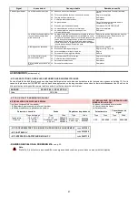
Anmerkung
Es wird empfohlen, den Brenner je nach benutz-
tem Gastyp gemäß den Angaben in der Tabelle
(B) einzustellen.

MAINTENANCE

Combustion
The  optimum  calibration  of  the  burner  requires
an analysis  of the  flue  gases. Significant  differ-
ences  with  respect  to  the  previous  measure-
ments  indicate  the  points  where  more  care
should be exercised during maintenance.

Gas leaks
Make  sure  that  there  are  no  gas  leaks  on  the
pipework between the gas meter and the burner.

Gas filter
Change the gas filter when it is dirty.

Combustion head
Open the burner and make sure that all compo-
nents of the combustion head are in good condi-
tion,  not  deformed  by  the  high  temperatures,
free of impurities from the surroundings and cor-
rectly positioned.

Flame present check (A)
The  burner  is  fitted  with  an  ionisation  system
which ensures that a flame is present. The mini-
mum  current  for  plant  operation  is  6  µA.  The
burner  provides  a  much  higher  current,  so  that
controls are not normally required. However, if it
is  necessary  to  measure  the  ionisation  current,
disconnect  the  plug-socket  on  the  ionisation
probe  cable  and  insert  a  direct  current  micro-
amperometer  with  a  base  scale  of  100  µA.
Carefully check polarities!

Burner
Check for excess wear or loose screws.
Clean the outside of the burner.

Combustion
In  case  the  combustion  values  found  at  the
beginning of the intervention do not respect the
standards in force or, in any case, do not corre-
spond  to  a  proper  combustion,  contact  the
Technical Assistant and have him carry out the
necessary adjustments.
Note
We recommend calibrating the burner - depend-
ing on the type of gas utilised - according to the
indications given in table (B).

ENTRETIEN

Combustion
Pour  obtenir  un  réglage  optimal  du  brûleur,  il
faut  effectuer l'analyse  des  gaz  d'échappement
de la combustion à la sortie de la chaudière. Les
différences significatives par rapport au contrôle
précédent  indiqueront  les  points  où  l'opération
d'entretien devra être plus approfondie.

Fuites de gaz
Contrôler  l'absence  de  fuites  de  gaz  sur  le
conduit compteur-brûleur.

Filtre du gaz
Remplacer le filtre du gaz lorsqu'il est encrassé.

Tête de combustion
Ouvrir le brûleur et contrôler si toutes les parties
de la tête de combustion sont intactes, ne sont
pas  déformées  par  les  températures  élevées,
sont exemptes d'impuretés provenant du milieu
ambiant et positionnées correctement.

Controle presence flamme (A)
Le  brûleur  est  muni  d'un  système  à  ionisation
pour  contrôler  la  présence  de  la  flamme.  Pour
faire fonctionner le boîtier de contrôle le courant
minimum est de 6 µA. Le brûleur produit un cou-
rant  nettement  supérieur  qui  ne  nécessite  nor-
malement d'aucun contrôle. Toutefois, si on veut
mesurer  le  courant  d'ionisation,  il  faut  décon-
necter  la  fiche-prise  placée  sur  le  câble  de  la
sonde  d'ionisation  et  connecter  un  microampè-
remètre  pour  courant  continu  de  100  µA  bas
d'échelle. 
Attention à la polarité!

Brûleur
Vérifier qu'il n'y ait pas d'usure anormale ou de
vis desserrées.
Nettoyer extérieurement le brûleur.

Combustion
Si  les  valeurs  de  la  combustion  relevées  au
début  de  l’intervention  ne  satisfont  pas  aux
normes  en  vigueur  ou  ne  permettent  pas  une
bonne  combustion,  contacter  le  Service  après-
vente  pour  qu’il  effectue  les  réglages  qui
s’imposent.
Note
Il est conseillé de régler le brûleur selon le type
de gaz utilisé, voir les indications fournies dans
le tableau (B).

Summary of Contents for RS 300/P BLU

Page 1: ...etien Bruciatori di gas ad aria soffiata Gas Gebl sebrenner Forced draught gas burners Br leurs gaz air souffl Funzionamento modulante Modulierender Betrieb Modulating operation Fonctionnement modulan...

Page 2: ......

Page 3: ...tti sono marcati come indicato a seguire CE 0085BO0341 RS 300 P BLU 849 T CE 0085BO0341 RS 400 P BLU 850 T La qualit viene garantita mediante un sistema di qualit e management certificato secondo UNI...

Page 4: ...end angegeben gekennzeichnet CE 0085BO0341 RS 300 P BLU 849 T CE 0085BO0341 RS 400 P BLU 850 T Die Qualit t wird durch ein gem UNI EN ISO 9001 zertifiziertes Qualit ts und Managementsystem garantiert...

Page 5: ...ility Such products are marked as follows CE 0085BO0341 RS 300 P BLU 849 T CE 0085BO0341 RS 400 P BLU 850 T The quality is guaranteed by a quality and management system certified in accordance with UN...

Page 6: ...oduits sont marqu s comme indiqu par la suite CE 0085BO0341 RS 300 P BLU 849 T CE 0085BO0341 RS 400 P BLU 850 T La qualit est garantie gr ce un syst me de qualit et de gestion certifi conforme UNI EN...

Page 7: ...fen 42 Zubeh r 43 Normalbetrieb Flammenf hlzeit 48 Anhang Schaltplan 50 D CONTENTS Technical data page 8 Electrical data 8 List of available models 9 Burner description 13 Description of panel board 1...

Page 8: ...3 4 38 7 FUNZIONAMENTO Intermittente IMPIEGO STANDARD Caldaie ad acqua a vapore ad olio diatermico TEMPERATURA AMBIENTE C 0 40 TEMPERATURA ARIA COMBURENTE C max 60 RUMOROSIT 3 PRESSIONE SONORA POTENZA...

Page 9: ...zione elettrica del sistema 3 400 50 3 380 60 Tensione ausiliari 230 50 60 R S 300 P TC Emissione Classe 1 EN267 EN676 MZ Classe 2 EN267 EN676 BLU Classe 3 EN267 EN676 MX Classe 1 EN267 Classe 3 EN676...

Page 10: ...B Intermittierend STANDARDEINSATZ Heizkessel mit Wasser Dampf diathermischem l RAUMTEMPERATUR C 0 40 TEMPERATUR VERBRENNUNGS LUFT C max 60 SCHALLDRUCKPEGEL 3 SCHALLDRUCKPEGEL SCHALLEISTUNG dB A 82 93...

Page 11: ...ltung in 72 Std Stromversorgung des Systems 3 400 50 3 380 60 Spannung der Hilfskreise 230 50 60 R S 300 P TC Emission Klasse 1 EN267 EN676 MZ Klasse 2 EN267 EN676 BLU Klasse 3 EN267 EN676 MX Klasse 1...

Page 12: ...3 4 38 7 18 26 33 4 38 7 OPERATION Intermittent STANDARD APPLICATIONS Boilers water steam diathermic oil AMBIENT TEMPERATUR C 0 40 COMBUSTION AIR TEMPERATURE C max 60 NOISE LEVELS 3 SOUND PRESSURE SOU...

Page 13: ...the system 3 400 50 3 380 60 Auxiliary voltage 230 50 60 R S 300 P TC Emission Class 1 EN267 EN676 MZ Class 2 EN267 EN676 BLU Class 3 EN267 EN676 MX Class 1 EN267 Class 3 EN676 FS1 3 400 50 230 50 60...

Page 14: ...6 33 4 38 7 18 26 33 4 38 7 FONCTIONNEMENT Intermittent EMPLOI STANDARD Chaudi res eau vapeur huile diathermique TEMPERATURE AMBIANTE C 0 40 TEMPERATURE AIR COMBURANT C max 60 NIVEAU DE BRUIT 3 PRESSI...

Page 15: ...72 heures Alimentation lectrique du syst me 3 400 50 3 380 60 Tension auxiliaires 230 50 60 R S 300 P TC mission Classe 1 EN267 EN676 MZ Classe 2 EN267 EN676 BLU Classe 3 EN267 EN676 MX Classe 1 EN267...

Page 16: ...ione del kit Regolatore di potenza RWF40 5 Pulsante di stop 6 Selettore spento automatico manuale 7 Selettore aumento diminuzione potenza 8 Segnalazione luminosa consenso alla par tenza 9 Segnalazione...

Page 17: ...rminal strip for kits 2 Relay outlet clean contacts 3 Ignition transformer 4 Bracket for mounting the power regulator RWF40 5 Stop push button 6 Dial for off automatic manual 7 Power dial for increase...

Page 18: ...ricambi INGOMBRO B misure indicative L ingombro del bruciatore riportato in fig B Tener presente che per ispezionare la testa di combustione il bruciatore deve essere aperto ruotando la parte posteri...

Page 19: ...nsulation screen 4 Screws to secure the burner flange to the boiler M 18 x 70 1 Instruction booklet 1 Spare parts list MAX DIMENSIONS B Approximate measurements The maximum dimensions of the burner ar...

Page 20: ...caldaia omologata CE e le dimen sioni della sua camera di combustione sono vicine a quelle indicate dal diagramma B Se invece il bruciatore deve essere applicato ad una caldaia non omologata CE e o c...

Page 21: ...ing does not pose any problems if the boiler is CE type approved and its combustion chamber dimensions are similar to those indicated in diagram B If the burner must be combined with a boiler that has...

Page 22: ...lio 4 La protezione deve consentire al boccaglio di essere estratto Per le caldaie con il frontale raffreddato ad acqua non necessario il rivestimento refratta rio 2 5 B se non vi espressa richiesta d...

Page 23: ...inserted between the boiler fettling 2 and the blast tube 4 This protective fettling must not compromise the extraction of the blast tube For boilers having a water cooled front the refractory fettlin...

Page 24: ...agrammi di fig C Per funzionamento su caldaie ad inversione di fiamma i tubi gas devono essere regolati nel foro in posizione 4 vedere Fig D 1 2 0 1 2 3 4 5 6 B A D3107 D3092 Sonda F hler Probe Sonde...

Page 25: ...ectrode and the probe are positioned as shown in figure A COMBUSTION HEAD SETTING B Loosen the screw 1 and turn the graduated sector 2 according diagrams C For operation on flame reversal boilers gas...

Page 26: ...l bruciatore da tabella C riferita a zero in camera di combu stione per la pressione reale misurata con un manometro ad U vedi fig A pag 24 aggiun gere la contropressione di caldaia Nota Per la regola...

Page 27: ...ressure down line from the filter P3 Pressure up line from the filter P4 Air pressure at combustion head PA Air pressure PC Combustion chamber pressure PG Gas pressure L Gas train supplied separately...

Page 28: ...ne di 90 in 30 s Non modificare la regolazione fatta in fabbrica alle 4 camme di cui dotato solo controllare che esse siano come sotto riportato Camma 1 blu 0 Limita la rotazione verso il minimo A bru...

Page 29: ...s delivery at the minimum SERVOMOTOR B Servomotor adjusts air damper by means of the gear system It rotates through 90 degrees in 30 seconds Do not alter the factory setting for the 4 cams simply chec...

Page 30: ...in modo che le farfalle aria risul tino completamente aperte Allentare la vite 2 A posta sotto l aspirazione del bruciatore e chiudere progressivamente la griglia 1 A fino ad ottenere la potenza rich...

Page 31: ...l tement ouvertes Desserrer la vis 2 A situ e sous l aspiration du br leur et fermer progressivement la grille 1 A pour obtenir la puissance voulue L tranglement en aspiration n est n cessaire qu au c...

Page 32: ...del pistone verso il basso nel cilindro determinando l apertura della valvola del gas Quando viene interrotta l alimentazione alla pompa la differenza di pressione a livello dell orifizio si riduce is...

Page 33: ...e moving the diaphragm and the attached spring loaded plug to the left closing the return flow path from the pressure chamber to the res ervoir This action causes the piston to move downward in the cy...

Page 34: ...essere montato o sostituito mentre la valvola gas sotto pressione L attuatore deve essere mon tato in modo che l indicatore di posizione della corsa sia chiaramente visibile Tutte le tubazioni colleg...

Page 35: ...e combustion chamber during the startup sequence It must always be taken into account that the bur ner outout decreases as the combustion cham ber pressure increases and vice versa INSTALLATION Warnin...

Page 36: ...a caratteristica di entita elevata occorre verificare nuovamente la regolazione del rapporto di pressione al 90 del funzionamento 6 Far funzionare il bruciatore alla potenza richiesta e limitare la po...

Page 37: ...l load or at 90 of the nominal load must be checked again and corrected if neces sary 6 Run the burner at the required output and limit the air damper position or adjust intake to a partial setting If...

Page 38: ...fine scala B Con il bruciatore funzionante alla potenza mas sima diminuire la pressione di regolazione girando lentamente in senso antiorario l appo sita manopolina fino al blocco del bruciatore Girar...

Page 39: ...ing performed all the other burner adjust ments with the pressure switch set at the end of the scale B With the burner operating at maximum output decrease adjustment pressure by slowly turning the re...

Page 40: ...are la corrente di ionizzazione bisogna disinserire la spina presa posta sul cavo della sonda di ionizzazione ed inserire un microamperometro per corrente con tinua da 100 A fondo scala Attenzione all...

Page 41: ...6 A The burner provides a much higher current so that controls are not normally required However if it is necessary to measure the ionisation current disconnect the plug socket on the ionisation probe...

Page 42: ...ria Se la temperatura o la pressione bassa per cui il TR chiuso il bruciatore aumenta pro gressivamente la potenza fino al valore MAX tratto C D Se poi la temperatura o la pressione aumenta fino all a...

Page 43: ...sure is low and the TR is consequently closed the burner pro gressively increases its output to the MAX value section C D If subsequently the temperature or pressure increases until TR opens the burne...

Page 44: ...mpeggi Il bruciatore non si avvia ed appare il blocco 14 Pressostato aria in posizione di funzionamento Regorarlo o sostituirlo Il bruciatore si avvia e poi si arresta in blocco Pressostato aria non c...

Page 45: ...de e si ferma il bruciatore La pres sione torna ad aumentare il pressostato chiude e fa ripetere il ciclo di avviamento E cos via Ridurre la pressione di intervento del pres sostato gas di minima Sost...

Page 46: ...Luftdruckw chter in Betriebsstellung Einstellen oder auswechseln Der Brenner f hrt an und es erfolgt eine St rabschaltung Luftdruckw chter schaltet nicht um weil Luftdruck nicht ausreichend 15 Luftdr...

Page 47: ...irkt die ffnung des Druckw chters Dadurch schlie t sich das Ventil sofort wieder und der Brenner stellt sich ab der Druck steigt an der Druckw chter schlie t und setzt eine neue Anfahrphase in Gang un...

Page 48: ...itch on and the lockout appears 14 Air pressure switch in operating position Adjust or replace The burner switches on but then stops in lockout Air pressure switch inoperative due to insufficient air...

Page 49: ...ely closes and the burner comes to a halt Pressure increases again the pressure switch closes again and the ignition cycle is repeated And so on Reduce the minimum gas pressure switch intervention pre...

Page 50: ...du pressostat obstru Nettoyer 17 T te mal r gl e R gler 18 Haute pression dans le foyer Raccorder le pressostat air l aspiration du ventilateur Blocage durant la pr ventila tion 19 Contacteur de comma...

Page 51: ...ro voque l ouverture temporaire du pressostat la vanne se ferme aussit t et le br leur s arr te La pression aug mente nouveau le pressostat se ferme et fait r p ter le cycle de d marrage Et ainsi de s...

Page 52: ...ie GR NE LED zu blinken wie auf der Abbildung unten dargestellt Die Impulse der LED erzeugen ein Signal mit zirka 3 Sekunden Unterbrechung Die Anzahl der Impulse zeigt die DETEKTIONSZEIT des F hlers a...

Page 53: ...es impulsions de la LED sont un signal qui se r p te environ toutes les 3 secondes Le nombre des impulsions identifiera le TEMPS DE D TECTION de la sonde de l ouverture des vannes gaz d apr s le table...

Page 54: ...2 operational layout Sch ma fonctionnel RMG M88 62A2 8 Schema funzionale RMG M88 62A2 Betriebsschema RMG M88 62A2 RMG M88 62A2 operational layout Sch ma fonctionnel RMG M88 62A2 Kit regolatore di pote...

Page 55: ...HHI 4 8V 1 3 1 5 5 3 X 3 5 4 U6V 4 U7V U6V1 B WWU4 2 2 U 2 U 2 U 12 BC U 1 U CAB U 1BD E FA1 C U E C U 12 U F F B U FB U B3 U FB B BC C U B U BC2F U BC3 A1 C U A3 U 1 U A CF 1B1 AC U CB1 F U CB1 F U C...

Page 56: ...5 7 X 4 X5 Y4 X6 34 G5HHI U5V 6 4 5 7 7V 2 1 2 4 4 1 1 4 B U5V B U6V U5V2 A 5XXUB 3 3 U 3 U 3 U 23 AC U 2 U C A U Y2AD E F 2 C U E CY U _23 U F F A U FA U A1 U FA A AC C U A U AC3F U AC1 Y 2 C U Y 1...

Page 57: ...B 4 79 B 4 39 4 G 7 B 4 35 B B 5 H3 A7 G I 3 B A7 H B J39 7 B I7 4 I G K7 67 B I 77 B K7 B I L 6 G B 76 B 9I7 B H G 4 3 5 B H 7 B 4 3 5 B H7 IG 3 3 5 B 3 I7 B 3 I7 B 3 I7 K G K 7 B K 7 B K 7 B K 7 IAG...

Page 58: ...E5 A E5 50 0 1 29 7 2 4 4 A1E50 A E6 F2 F3 7 G G 3 4 4 A0E5 A1E51 A0E7 29 A0E7 A0E6 HHAC 5 I 5 A 5 8 A 5 8 A 5 4 5 I 8 A 5 46 A A 6 J4 D8 I B 4 A D8 J A K4 8 A B8 5 B I 8 78 A B 88 A 8 A B L 7 I A 87...

Page 59: ...55...

Page 60: ...2 G5 4 G5 7 3 7 C C A G6 5 G6 6 E5F9 E5F9 G7 E6F8 7 N 7B E 7B E 7B E 7B 70 N CA E 7B 80 E A C E 8 O C N D BBA E BBAO E P E D B7 D N C9 E DC E C2 E DCQ C9 N CA A E C 9 E CA D E CA2 O N 7 8A E O 2 E 7B...

Page 61: ...G78 19 1 3 1 C3D8 19 C3D7 18 C3D8 C3D0 C3D0 C3D0 G J 7 K 7 C 7 C 7 C 7 0 7 K 4A C 7 08 C A 4 C 8 L04 E K B 0 A C E AL C M0 C B 7 B K I 49 C B4 C I 4 C B4N 49 K 4A A C 4 9 C 4A B C 4A L K 7 0 8A C L C...

Page 62: ...L Z KE E LE SZ S L QL T QL T Q L T QGL M RP T QGH T MPOR T HJ GRN W SOGQQP T W QQP T GLM T S Q SM _ RI T SR M T _ RV T SR M RI RP P T R I T RPLS T RPV J OGMHP T JOV T QGMH T O PS GRGMHOP T PRGMS T PR...

Page 63: ...G95 EM 95 U4 I DDQ 5 Y B 6 B H 45 505 65L6 A B 45 B H B 56 B6 BM 5 OB HB L6 HB 6 B H 45Y 5HZ 0 BL6 H 4 ANB 45 B M B G B B B G 4 L6W H 5 5 H6 0 6 54 AB 5 H 6 6 0 65 HB 566HMO 6G A5 0 65 B 5 G B5L 156...

Page 64: ...T fBg Z4 f g 8 9 A B C C 2 94 h 1h 6 G 6 6 9 h 1h WSOU 2M WYON BFD 9G G3 G6 G 94 9 9G G6 G3 i T WO SMX QU OX YQW WOMPR N W 9 B8 j A Z4 i G 2 i i G 3 7 0 G3 j 8 G6 G 6 2 G 6 G 6 07 07 B Z4 0 6 9 6 9 Z...

Page 65: ...3 W 1 1 2W 3 435 4 SU4 5XENYZZZ SU4 EW S3 W 41 5XENYZZZ S 31 31 3P 3R 3Q 1 1 4 14 1 L 45W 1 SL W 5 SUX 5V 24 11W 2411WX _ 4 41 45T4 544 453 5a 5T 5W W 54T 5W 4 5W3 XU SW XU 34 1 S X4 W 5 S W W5 4 W5...

Page 66: ...0 mA 4 20 mA BA1 Eingang in Gleichstrom DC 0 20 mA 4 20 mA f r die nderung des Fern Sollwertes BP Druckf hler BP1 Druckf hler BR Potentiometer f r Fern Sollwert BT1 Thermoelementf hler BT2 F hler Pt10...

Page 67: ...nsigne distance BP Sonde de pression BP1 Sonde de pression BR Potentiom tre valeur de consigne distance BT1 Sonde avec thermocouple BT2 Sonde Pt100 2 fils BT3 Sonde Pt100 3 fils BT4 Sonde Pt100 3 fils...

Page 68: ...Con riserva di modifiche nderungen vorbehalten Subject to modifications Sous r serve de modifications RIELLO S p A I 37045 Legnago VR Tel 39 0442 630111 http www riello it http www riello com...

Reviews: