background image

20040407

12 

GB

Installation

4.1

Notes on safety for the installation

After carefully cleaning all around the area where the burner will be
installed, and arranging the correct lighting of the environment, pro-
ceed with the installation operations.

4.2

Handling 

The packaging of the burner includes a wooden platform, so it is
possible to move the burner (still packaged) with a transpallet truck
or fork lift truck.

4.3

Preliminary checks

Checking the consignment

4.4

Boiler plate

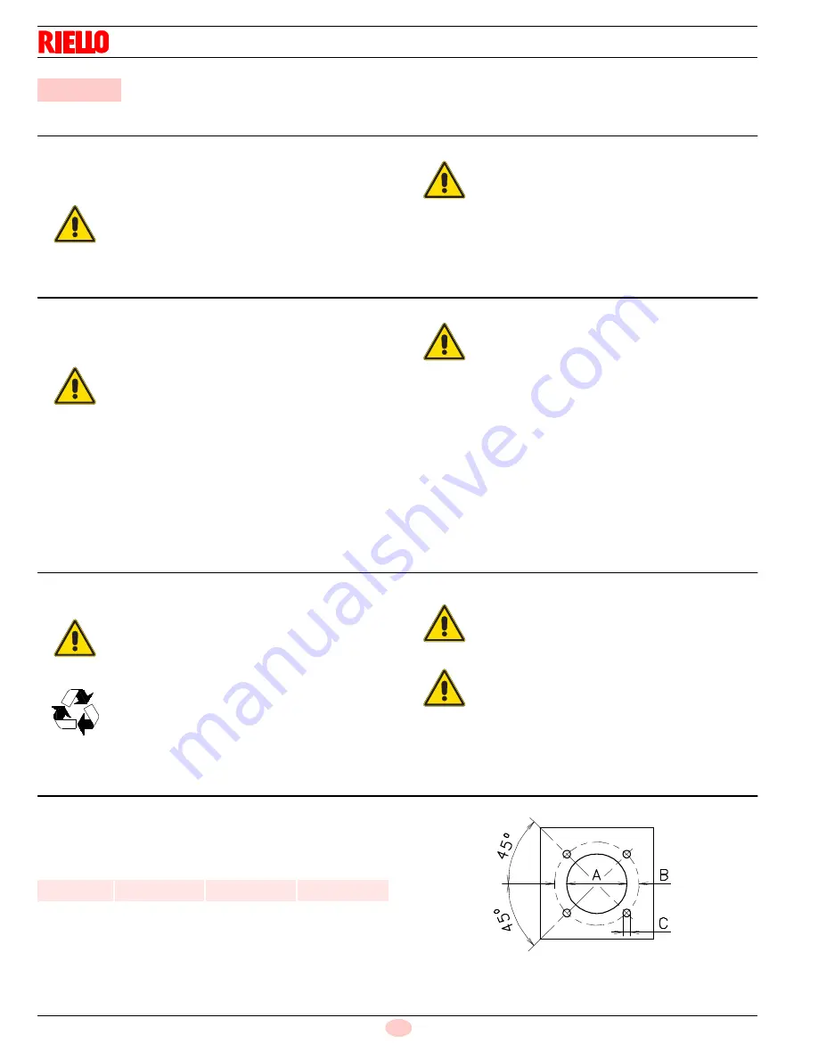
Drill the combustion chamber mounting plate as shown in Fig. 7.

The position of the threaded holes can be marked using the head
gasket supplied with the burner.

Tab. G

4

Installation

DANGER

All  the  installation,  maintenance  and  disassembly
operations  must  be  carried  out  with  the  electricity
supply disconnected.

WARNING

The installation of the burner must be carried out by
qualified personnel, as indicated in this manual and
in compliance with the standards and regulations of
the laws in force.

WARNING

The handling operations for the burner can be high-
ly dangerous if not carried out with the greatest at-
tention:  keep  any  unauthorised  people  at  a
distance; check the integrity and suitableness of the
available means of handling.

Check also that the area in which you are working
is empty and that there is an adequate escape area
(i.e. a free, safe area to which you can quickly move
if the burner should fall).

During the handling, keep the load at not more than
20-25 cm from the ground.

CAUTION

After  positioning  the  burner  near  the  installation
point,  correctly  dispose  of  all  residual  packaging,
separating the various types of material.

Before proceeding with the installation operations,
carefully clean all around the area where the burner
will be installed.

CAUTION

After removing all the packaging, check the integrity
of the contents. In the event of doubt, do not use the
burner; contact the supplier.

The  packaging  elements  (wooden  cage  or  card-
board box, nails, clips, plastic bags, etc.) must not
be abandoned as they are potential sources of dan-
ger and pollution; they should be collected and dis-
posed of in the appropriate places.

WARNING

The output of the burner must be within the boil-
er’s firing rate;

WARNING

A  burner  label  that  has  been  tampered  with,  re-
moved or is missing, along with anything else that
prevents  the  definite  identification  of  the  burner
makes  any  installation  or  maintenance  work  diffi-
cult.

inch

A

B

C

RS 45/M

9

/

32“

13

/

16“

3

/

8

 W

D455

Fig. 7

Summary of Contents for RS 45/M

Page 1: ...20040407 2 11 2014 Installation use and maintenance instructions Forced draught gas burner Progressive two stage or modulating operation CODE MODEL 20039998 RS 45 M GB...

Page 2: ......

Page 3: ...n 12 4 1 Notes on safety for the installation 12 4 2 Handling 12 4 3 Preliminary checks 12 4 4 Boiler plate 12 4 5 Blast tube length 13 4 6 Securing the burner to the boiler 13 4 7 Ignition pilot adju...

Page 4: ...flame signal with a volt ohmmeter 25 5 6 4 Flame signal measurement 25 5 6 5 Inadequate flame signal 25 5 7 Final checks with the burner working 26 6 Maintenance 27 6 1 Notes on safety for the mainten...

Page 5: ...car ried out correctly may cause damage to the ma chine and or injury to people DANGER DANGER LIVE COMPONENTS This symbol indicates operations which if not car ried out correctly lead to electric shoc...

Page 6: ...of damage to things or injury to peo ple if such damage injury was due to any of the following causes incorrect installation start up use and maintenance of the burner improper incorrect or unreasona...

Page 7: ...nce Only those parts envisaged by the manufacturer can be replaced 2 2 Personnel training The user is the person body or company that has acquired the ma chine and intends to use it for the specific p...

Page 8: ...1 High MBtu hr kW 717 2037 1969 210 597 577 Low MBtu hr kW 341 100 Fuel Natural or propane gas Max delivery Pressure at maximum delivery 2 natural gas SCFH WC 2037 5 31 Operation Low high low or modu...

Page 9: ...res the burner to be opened and the rear part withdrawn on the slide bars The maximum dimension of the burner when open without casing is give in measurement H Tab E 1 Blast tube short long obtainable...

Page 10: ...tude variation reference temper ature 68 F 20 C To get the combined correction in case of different air temper ature a compensation of 1000 ft each 20 F 305 m each 11 C is applicable 100 ft 2 F Exampl...

Page 11: ...908 2 875 8 843 5 811 85 779 8 747 8 Average barometric pressure 68 F w c 399 394 385 371 358 345 332 320 307 294 CORRECTED BURNER AIR PRESSURE ACCORDING TO ALTITUDE Altitude Rated Pressure m a s l 0...

Page 12: ...the best results are obtained in terms of low NOx emissions The maximum thickness of the boiler s front door must not ex ceed 8 see Fig 4 3 9 Minimum furnace dimensions The firing rates were set in re...

Page 13: ...pilot light and lock out reset button 24 AUTO MAN switch 25 RWF40 terminal board X3 26 K1 relay 27 K3 relay 28 K min relay 29 K max relay 30 Optional holes 31 Fan motor with capacitor 32 Ground termi...

Page 14: ...at a distance check the integrity and suitableness of the available means of handling Check also that the area in which you are working is empty and that there is an adequate escape area i e a free sa...

Page 15: ...lation must not compromise the extraction of the blast tube For boilers having a water cooled front the insulation 4 5 Fig 8 is not required unless it is required by the boiler manu facturer 4 6 Secur...

Page 16: ...tified is aligned with index 3 Central air adjustment R2 Fig 10 Turn choke 5 until the notch identified is aligned with screw 4 Tighten the screws 1 and 4 fully down Example Burner output 1515 MBtu hr...

Page 17: ...otates through 90 degrees in 25 seconds Do not alter the factory setting for the cams simply check that they are set as indicated below Red cam 90 Limits rotation toward maximum position When the burn...

Page 18: ...regulator 4 Low gas pressure switch 5 1st safety shut off valve 6 2nd safety shut off valve 7 Standard issue burner gasket with flange 8 Gas adjustment butterfly valve 9 Burner Explosion danger due to...

Page 19: ...measured at test point 1 Fig 16 find the nearest pressure value to your result in column 2 for the burner in question read off the corresponding output on the left Example with natural gas G20 Maximum...

Page 20: ...ication label and in this manual Do not invert the neutral with the phase in the electrical supply line Any inversion would cause a lockout due to firing failure The electrical safety of the device is...

Page 21: ...m Manager Software Functions provided by the RM7840 include automatic burner se quencing flame supervision system status indication system or self diagnostics and troubleshooting SPECIFICATIONS Electr...

Page 22: ...s must be observed The RM7840 is a safety device Do not open interfere with or modify the unit The Manufacturer will not assume responsibility for any damage resulting from unauthorized interference W...

Page 23: ...the motor is 400V To reset in the case of an intervention of the thermal relay press the button RESET Fig 20 The button STOP Fig 20 opens the NC 95 96 contact and stops the motor To test the thermal r...

Page 24: ...the switch to position ON Fig 26 Turn the switch to position MAN Fig 26 for manual opera tion or AUTO for automatic operation NOTE For further information please refer to the specific instruction of t...

Page 25: ...let gas pres sure Adjusting air delivery Progressively adjust the end profile of cam 4 Fig 27 by turning the cam adjustment screws as they appear through the access opening 6 Turn the screws clockwise...

Page 26: ...he air pressure switch from switching switching may be obtained by fitting a second pipe between the air pressure switch and the suction inlet of the fan In this way the air pressure switch operates a...

Page 27: ...is not too lean Make sure the optical detector is properly sighting the flame If necessary resight or reposition the detector If you cannot obtain proper operation replace the plugin amplifier If you...

Page 28: ...d of scale position if installed Rotate the air pressure switch knob to the maximum end of scale position The burner must stop in lockout Switch off the burner and disconnect the voltage Disconnect th...

Page 29: ...fitting 7 Fig 35 UV scanner Clean the glass cover from any dust that may have accumulated In order to reach the UV scanner unscrew the screw 1 Fig 32 and extract the flame sensor with the relevant su...

Page 30: ...the linkag es joints and cam Flame inspection window Clean the flame inspection window Fig 33 Combustion Adjust the burner if the combustion values found at the beginning of the operation do not compl...

Page 31: ...6 and pull the burner back on slide bars 5 by about 4 disconnect the electrode wires and then pull the burner com pletely back unscrew the pin 8 from the connection 9 push ahed the connection to the e...

Page 32: ...arrange in the correct site the extention bars 4 Fig 35 refit screws 2 on slide bars 3 Fig 35 secure the burner to the sleeve by tightening screw 1 connect the tie rod 6 to the connection 7 WARNING Wh...

Page 33: ...Spare parts 79 77 78 76 75 72 38 39 40 34 35 32 33 31 30 36 71 29 52 47 48 50 49 46 13 12 69 7 9 2 22 43 44 4 3 60 1 10 11 6 23 25 26 68 67 62 64 66 63 64 14 15 74 16 24 58 57 65 54 53 56 55 45 73 42...

Page 34: ...R B 21 20027021 SWITCH C 22 3013008 SERVOMOTOR B 23 3012993 MOTOR C 24 20027028 SCREW SPACER 25 3003891 CONNECTOR C 26 3012948 AIR PRESSURE SWITCH B 27 20027423 SWITCH 28 20010962 BUTTON A 29 3003794...

Page 35: ...ELBOW 59 20010969 RELAY 60 20027453 HALF SHELL 61 20027020 LIGHT SIGNAL C 62 3003888 SPACER 63 3003883 COWLING 64 3006098 PIN JOINT 65 3003203 PISTON SEAL 66 3003881 TIE ROD 67 3012062 CAM ASSEMBLY 68...

Page 36: ...Gas train according to UL Standards B Appendix Accessories Burner Standard length Length obtainable with kit Code RS 45 M 9 1 32 13 15 16 20027083 WARNING The installer is responsible for the supply a...

Page 37: ...Fire High Fire Control Power Supply CO Low Fire High Fire Burner Firing Rate NOX Low Fire High Fire Manifold Pressure Net Stack Temp Low Fire High Fire Pilot Flame Signal Comb Efficiency Low Fire Hig...

Page 38: ......

Page 39: ......

Page 40: ...ORTH AMERICA 35 Pond Park Road 1 800 4 RIELLO 2165 Meadowpine Blvd Hingham Massachusetts 1 800 474 3556 Mississauga Ontario U S A 02043 Canada L5N 6H6 http www riello ca RIELLO S p A I 37045 Legnago V...

Reviews: