Start-up, calibration and operation of the burner
25
20040407
GB
5.6.3
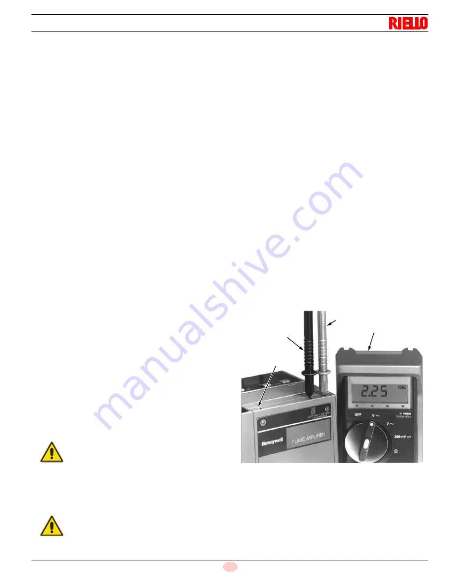
Measuring flame signal with a volt ohmmeter
Two test jacks, positive and negative (Com) are accessible on the
top of the amplifier when plugged into the 7800 SERIES Relay
Module. These jacks are provided for monitoring flame signal
strength. Use a one megohm/volt meter to measure the flame
signal strength. Connect the positive meter lead (red) to the
positive (+) amplifier test jack and the negative meter lead (black)
to the negative (-) amplifier test jack. The test jacks use standard
0.180 inch diameter voltmeter probes. A minimum 1.25 Vdc flame
signal is required.
The flame signal for the pilot alone, the main burner flame alone,
and both together must be steady and a minimum of 1.25V. If the
flame signal is unsteady, or less than the minimum acceptable
voltage, check the flame detector installation and circuitry in the
following procedure.
➤
1. Check the supply voltages at terminals (L1) and L2 (N).
Make sure the master switch is closed, connections are cor-
rect, and the power supply is of the correct voltage and fre-
quency and is sinusoidal.
➤
Check the detector wiring for defects including:
– Incorrect connections.
– Wrong type of wire.
– Deteriorated wire.
– Open circuits.
– Short circuits.
– Leakage paths caused by moisture, soot or accumulated
dirt.
➤
For a flame rod, make sure:
– There is enough ground area.
– The flame rod is properly located in the flame.
– Temperature at the flame rod insulator is no greater than
500°F (260°C).
➤
For all optical detectors, clean the detector viewing window,
lens, and inside of the sight pipe as applicable.
➤
With the burner running, check the temperature at the detec-
tor. If it exceeds the detector maximum rated temperature:
– Add a heat block to stop conducted heat traveling up the
sight pipe.
– Add a shield or screen to reflect radiated heat.
– Add cooling (refer to sight pipe ventilation in the detector In-
structions).
➤
Make sure that the flame adjustment is not too lean.
➤
Make sure the optical detector is properly sighting the flame.
➤
If necessary, resight or reposition the detector.
➤
If you cannot obtain proper operation, replace the plugin
amplifier.
➤
If you cannot yet obtain proper operation, replace the flame
detector.
5.6.4
Flame signal measurement
Flame signal can be measured at the Flame Signal Test Jacks, see
(Fig. 31), and at the Keyboard Display Module.
5.6.5
Inadequate flame signal
If a satisfactory flame signal cannot be obtained while adjusting the
sighting position of the detector, perform the procedures indicated
in steps 1 through 7. Bother difficulties are encountered in the sys-
tem, refer to Troubleshooting in the Instructionsfor the appropriate
Honeywell Flame Safeguard Control.
➤
Check for proper line voltage. Make sure the master switch is
closed, connections are correct, and power supply is the cor-
rect voltage and frequency.
➤
Check the detector wiring for defects, including:
•
incorrect connections.
•
wiring type or size of wire.
•
deteriorated wire.
•
open circuits.
•
short circuits.
•
leakage paths caused by moisture, soot, or dirt.
➤
With the burner running, check the temperature at the detec-
tor. When it exceeds 215’ F [ 102’ C]:
•
use a heat block if using a Flame Detector.
•
add the additional insulation between the wall of the combus-
tion chamber and the detector.
•
add a shield or screen to reflect radiated heat away from the
detector, or
•
add cooling (refer to Sight Pipe Ventilation.
➤
Remove the detector and clean the viewing window with a
soft, clean cloth.
➤
Clean the inside of the sight pipe (if one is used) before rein-
stalling the detector.
➤
If the flame signal continues to be too low, replace the plug-in
amplifier (if the control has one).
➤
If you still cannot obtain a proper flame signal, replace flame
detector or UV radiation sensing tube.
WARNING
If you make any changes to the flame detection sys-
tem, repeat all required Checkout tests in the In-
structions for the applicable Relay Module.
WARNING
Equipment Damage Hazard.
Improper wiring can destroy ultraviolet sensing tube
Fig. 31
S8157
Positive (+) meter lead
One megohm/voltmeter
Negative (-)
meter lead
Flame simulator
test jack


