54
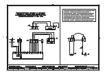
KEY TO ELECTRICAL LAYOUT
A
-
Electrical control box
B
-
Radio noise filter
+BB
-
Components on burners
+BC
-
Components on boiler
BP
-
Pressure probe
BT
-
Three–wire probe Pt100
CN1
-
Ionisation probe connector
CPI
-
Closed position indicator
F1
-
Fan motor thermal relay
H
-
Remote lockout signalling
IN
-
Manual burner stop switch
ION
-
Ionisation probe
h1
-
Hour counter
KM
-
Motor contact maker
MV
-
Fan motor
PA
-
Air pressure switch
PGM
-
Maximum gas pressure switch
PGMin
-
Low gas pressure switch
Q1
-
Three phase knife switch
Q2
-
Single–phase knife switch
RS
-
Remote reset button
S1
-
Unlit / automatic/ manual selector switch
S2
-
Power increase/decrease selector switch
SM
-
Servomotor
SV2
-
V2 Switch
TA
-
Ignition transformer
TL
-
Limit thermostat/pressure switch
TR
-
Adjustment thermostat/pressure switch
TS
-
Safety thermostat/pressure switch
UV
-
UV Photocell
Y
-
Valve assembly
XMB
-
Terminal board for RWF... Kit
XPG
-
Maximum gas pressure switch socket
XP4
-
4-pole socket
XP5
-
5-pole socket
XP6
-
6-pole socket
XP7
-
7-pole socket
XTM
-
Shelf earth
X1
-
Terminal board
X4
-
4-pin plug
X5
-
5-pin plug
X6
-
6-pin plug
X7
-
7-pin plug
LÉGENDE SCHÉMAS ELECTRIQUE
A
-
Coffret de sécurité
B
-
Protection contre parasites radio
+BB
-
Composants sur brûleurs
+BC
-
Composants sur chaudière
BP
-
Sonde de pression
BT
-
Sonde Pt100 à 3 fils
CN1
-
Connecteur sonde d’ionisation
CPI
-
Closed position indicator
F1
-
Relais thermique moteur ventilateur
H
-
Signalisation mise en sécurité remoto
IN
-
Interrupteur arrêt manuel brûleur
ION
-
Sonde d’ionisation
h1
-
Compteur d’ heures
KM
-
Contacteur moteur
MV
-
Moteur ventilateur
PA
-
Pressostat air
PGM
-
Pressostat gaz maxi
PGMin
-
Pressostat gaz mini
Q1
-
Disjoncteur triphasée
Q2
-
Disjoncteur monophasée
RS
-
Bouton de déblocage du brûleur à distance
S1
-
Sélecteur: éteint / automatique / manuel
S2
-
Sélecteur: augmentation / diminution puissance
SM
-
Servomoteur
SV2
-
interupteur V2
TA
-
Transformateur d’allumage
TL
-
Thermostat/ Pressostat de limite
TR
-
Thermostat/ Pressostat de réglage
TS
-
Thermostat/ Pressostat de sécurité
UV
-
Cellule photoélectrique UV
Y
-
Groupe vannes
XMB
-
Plaque à bornes pour Kit RWF...
XPG
-
Prise pressostat gas maxi
XP4
-
Prise 4 pôles
XP5
-
Prise 5 pôles
XP6
-
Prise 6 pôles
XP7
-
Prise 7 pôles
XTM
-
Terre support
X1
-
Plaque à bornes
X4
-
Fiche 4 pôles
X5
-
Fiche 5 pôles
X6
-
Fiche 6 pôles
X7
-
Fiche 7 pôles
Summary of Contents for RS 50/M
Page 50: ...50...
Page 52: ...52 0 0 0 1 0 0 0 0 0 0 0 0 0 0 0 1 0 222 3 3 4 5 6 7 2...
Page 55: ......


