20040563
26
GB
Installation
5.11
Thermal relay adjustment
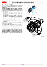
The thermal relay serves to avoid damage to the motor due to an
excessive absorption increase or if a phase is missing.
For calibration, refer to the table in the circuit diagram.
The protection is in any case ensured even if the minimum value of
the thermal relay scale is over the rating absorption of the motor.
This occurs when the motor power supply is 400 V. To reset, in case
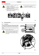
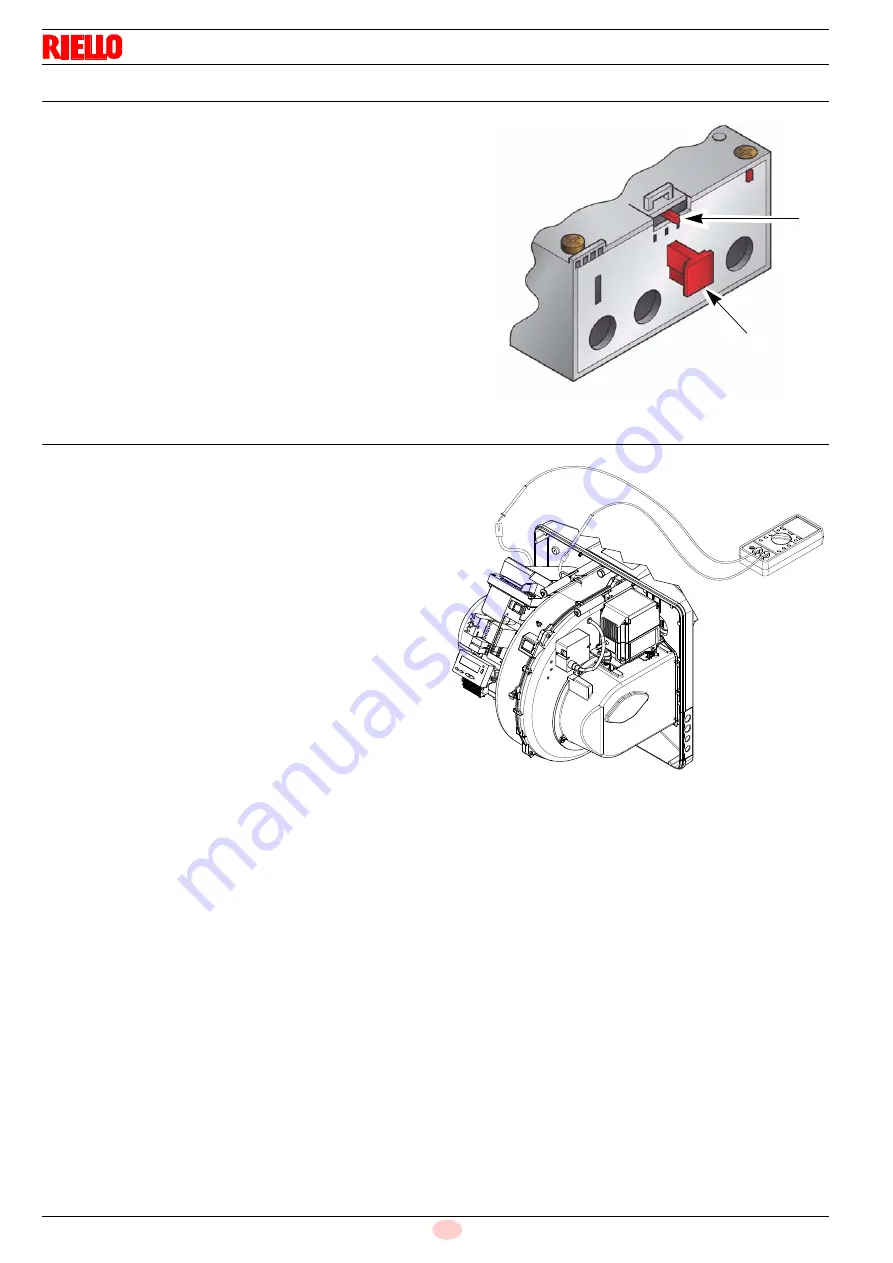
of an intervention of the thermal relay, press button 1)(Fig. 23).
5.12
Measuring the ionisation current
The burner is fitted with an ionisation system to check that a
flame is present.
The minimum current for control box operation is 4 µA. The burn-
er provides a much higher current, so controls are not normally
required.
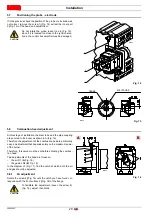
However, if it is necessary to measure the ionisation current, dis-
connect the plug-socket on the ionisation probe cable and insert a
direct current microammeter with a base scale of 100 µA (Fig. 24).
Carefully check the polarities!
Fig. 23
2
1
D8267
D8154
Fig. 24
Summary of Contents for RS 55/E BLU
Page 2: ...Translation of the original instructions Traducci n de las instrucciones originales...
Page 40: ......
Page 78: ...20040563 38 Appendix Ap ndice...
Page 79: ...39 20040563 Appendix Ap ndice...
Page 80: ...20040563 40 Appendix Ap ndice...
Page 81: ...41 20040563 Appendix Ap ndice...
Page 82: ...20040563 42 Appendix Ap ndice...

