background image

21 

20141167

GB

Installation

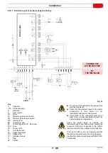
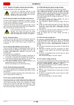
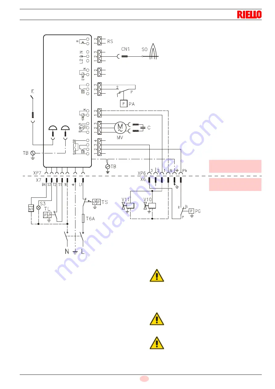
5.10.1 Electrical system carried out by the factory

Key

C

Capacitor

CN1

Probe connector

E

Electrode

h..

Hour counter

MV

Motor

PA

Minimum air pressure switch.

PG 

Minimum gas pressure switch

RS

Remote reset

SO

Ionisation probe

S3

Lockout signal (230V - 0.5A max.)

T6A

Fuse

TB

Burner earth

TL

Limit thermostat

TS

Safety thermostat

V10

Safety valve

V11

Adjustment valve

X..

Plug

XP..

Socket

230V 

~ 50 Hz

CARRIED OUT

AT THE FACTORY

Fig. 16

BY

THE INSTALLER

D4626

CONTROL BOX

Main 

switch

ATTENTION

Do not invert the neutral with the phase in the
electrical supply line.

Check that the electrical supply of the burner
corresponds to that shown on the
identification label and in this manual.

The section of the conductors must be at
least 1mm

2

. (Unless requested otherwise by

local standards and legislation).

ATTENTION

Check the burner stops by opening the
thermostats and check it locks out by opening the
connector (CN1)(Fig. 16) inserted in the probe's
red wire, located on the outside of the control box.

CAUTION

If the cover is still on, remove it and proceed with
the electric wiring following the wiring diagrams.
Use flexible cables in compliance with EN 60 335-
1 standards.

Summary of Contents for RS5F

Page 1: ...s Instrucciones de instalaci n uso y mantenimiento 20141167 1 01 2018 Forced draught gas burners Quemadores de gas con aire soplado One stage operation Funcionamiento a 1 llama CODE C DIGO MODEL MODEL...

Page 2: ...Translation of the original instructions Traducci n de las instrucciones originales...

Page 3: ...Instructions to avoid burnout or bad combustion of the burner 13 5 3 Handling 13 5 4 Preliminary checks 14 5 5 Operating position 14 5 6 Securing the burner to the boiler 15 5 7 Combustion head adjust...

Page 4: ...l notes 29 5 13 2 Block diagram for entering the menu 29 5 13 3 Switching off test 30 5 13 4 Post purging and continuous purging 30 5 13 5 Intermittent operation 30 5 13 6 Setting a long pre purging 3...

Page 5: ...ccording to the European Directives GAD 2009 142 EC Gas Devices Directive MD 2006 42 EC Machine Directive LVD 2014 35 EU Low Voltage Directive EMC 2014 30 EU Electromagnetic Compatibility Such product...

Page 6: ...ried out correctly may cause damage to the machine and or injury to people DANGER DANGER LIVE COMPONENTS This symbol indicates operations which if not carried out correctly lead to electric shocks wit...

Page 7: ...vent of damage to things or injury to people if such damage injury was due to any of the following causes incorrect installation start up use and maintenance of the burner improper incorrect or unreas...

Page 8: ...ntenance Only those parts envisaged by the manufacturer can be replaced 3 2 Personnel training The user is the person body or company that has acquired the machine and intends to use it for the specif...

Page 9: ...1981 Range Size Fuel Natural gas LPG Variations Electrical power supply 1 230 50 1 220 60 R S 5 1 230 50 BASIC DESIGNATION EXTENDED DESIGNATION 1 230V 50Hz 1 220V 60Hz F Light industrial process M Pro...

Page 10: ...ribed in EN ISO 3746 4 5 Electrical data Tab D Model RS5F Thermal output 1 kW Mcal h 160 330 13 76 28 38 Fuel Gas G20 NCV 8 12 kWh m3 7 000 10 340 kcal m3 Pressure min 20 mbar max 100 mbar Operation I...

Page 11: ...ng the boiler plate Pierce the closing plate of the combustion chamber as in Fig 2 The position of the threaded holes can be marked using the thermal insulation screen supplied with the burner Tab F F...

Page 12: ...he boiler conforms to EN 303 and the combustion chamber dimensions are similar to those shown in the diagram EN 676 For applications where the boiler does not conform to EN 303 or where the combustion...

Page 13: ...11 Burner equipment Flange with insulating gasket No 1 Screws and nuts for fixing the flange to the boiler No 4 Screw and nut for flange No 1 Remote reset connection No 1 7 pin plug No 1 Instructions...

Page 14: ...ve the control box from the burner it is necessary to Fig 5 disconnect all the connectors connected to it all the plugs the high voltage cables and the earth wire TB unscrew the screw A and pull the c...

Page 15: ...er If the smoke pipe is closed the burner must be drawn back till the extraction of blast tube from the furnace Before operating in this way take the voltage off 5 3 Handling The transport weight is g...

Page 16: ...the appropriate places ATTENTION The figure of the label Fig 6 is indicative Some of the data may be arranged in a different position ATTENTION A burner label that has been tampered with removed or i...

Page 17: ...ng the insulating gasket 3 in between using the screws 4 and if necessary the nuts 2 but keeping one of the two top screws 4 loose Insert the combustion head of the burner in the flange 5 tighten the...

Page 18: ...ombustion head according to the requirements of the specific boiler The burner is installed in a 210 kW boiler Considering an efficiency of 90 the burner must supply around 230 kW for this burner outp...

Page 19: ...ng Make sure that the plate 3 Fig 13 is always inserted in the flattening of the electrode 1 Rest the probe insulator 4 against the air diffuser 2 Tab I ATTENTION Respect the positions shown in Tab I...

Page 20: ...y point the cable clamp with pressure test point 1 and simple cable clamp 2 may need swapping over Consequently you must make sure the cable clamp 1 is positioned correctly the tube is positioned corr...

Page 21: ...2 2 2 10 mbar A pressure of 10 mbar column 1 corresponds in Tab J to an output of 330 kW This value serves as a rough guide the effective output must be measured at the gas meter Tab J To calculate th...

Page 22: ...is correctly connected to an efficient earthing system made according to current standards It is necessary to check this fundamental safety requirement In the event of doubt have the electrical syste...

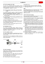
Page 23: ...switch ATTENTION Do not invert the neutral with the phase in the electrical supply line Check that the electrical supply of the burner corresponds to that shown on the identification label and in thi...

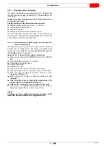
Page 24: ...ut due to lack of failure ts Safety time V1 Gas valve t2 t1 t3 t4i ts HT FM ID V1 LED P M LED t4l PG P SO SO POWER SUPPLY Signal not requested Green blink Lockout No flame during operation Green blink...

Page 25: ...ng time if the pressure switch does not change over within t3a there is a lockout max 15 t3r A recycle attempt is made if there is an air pressure drop during the pre purging stage there is then a loc...

Page 26: ...ximum number of cycle repetitions flame loss during operation RED fast blinking 0 2 0 2 Lockout due to a drop in air pressure after the pre purging was repeated due to a previous lack of air or 10 sec...

Page 27: ...closes the flame goes out and the start up sequence restarts If the switch off test is enabled the number of repetitions of the start up sequence see paragraph Recycle and limit of repetitions on pag...

Page 28: ...ss than 160V or more than 280V the burner stops interrupts the operating cycle and remains in stand by signalling a fault The fault is indicated by way of the blinking LED see paragraph Fault diagnost...

Page 29: ...in the absence of the heat request for a pre set time The burner switches off the flame when the heat request thermostat opens and the fuel supply to the gas valve stops The post purging function is...

Page 30: ...hours Together with the operating hours also the number of the burner s 1st stage valve openings is saved In the menu see paragraph Programming menu on page 29 it is possible to independently reset b...

Page 31: ...button No of blinks of the LED green Quitting the menu Test of Switching off 5s t 10s 2 blinks RED none none Automatic starting from the end of the blink Post purging Continuous purging 10s t 15s 1 G...

Page 32: ...purging function the exit menu occurs without saving the setting value If heat request stops during the led blinking occur exit menu but the setting value is stored 5 13 5 Intermittent operation Sequ...

Page 33: ...number of lockouts the operating hours the number of ignitions and recover the menu s default see paragraph Block diagram for entering the menu on page 29 Sequence for setting and restoring the param...

Page 34: ...ue to air pressure switch not closing after a heat request or after a recycle due to flame loss during operation After 15 seconds the air pressure is too low the head has been poorly adjusted The air...

Page 35: ...ion of the burner on the boiler the adjustment and testing must be carried out in compliance with the instruction manual of the boiler including control of the CO and CO2 concentration in the flue gas...

Page 36: ...will cause a reduction in the air flow rate and provoke polluting combustion Gas distributor Check at regular intervals that the holes of the gas head are not obstructed If they are clean them with a...

Page 37: ...given in Operating position on page 14 For accessing to the interior of the burner loosen the screws that secure the cover and proceed with the maintenance operation Check the operation Burner start...

Page 38: ...them The connections in the control box are wrongly inserted Check and connect completely all the plugs The air pressure switch is changed over to the operational position Replace the pressure switch...

Page 39: ...gain and so on Lower and set the pressure switch Faults Possible Causes Solution Fault Possible Causes Solution The burner locks out during operation Earth probe Check the right position and if necess...

Page 40: ...7 pin plug kit Gas trains in compliance with EN 676 Please refer to manual A Appendix Accessories Burner Standard length mm Extended head length mm Code RS5F 203 225 357 372 3001016 Burner Kit code fo...

Page 41: ...i n 13 5 4 Controles preliminares 14 5 5 Posici n de funcionamiento 14 5 6 Fijaci n del quemador a la caldera 15 5 7 Regulaci n cabezal de combusti n 16 5 7 1 Extracci n del grupo cabezal 16 5 7 2 Mon...

Page 42: ...ventilaci n y ventilaci n continua 30 5 13 5 Funcionamiento intermitente 30 5 13 6 Configuraci n de la pre ventilaci n larga 30 5 13 7 Visualizaci n del historial de bloqueos 31 5 13 8 Reset de los p...

Page 43: ...ivas Europeas GAD 2009 142 CE Directiva Aparatos de gas MD 2006 42 CE Directiva M quinas LVD 2014 35 UE Directiva Baja Tensi n EMC 2014 30 UE Compatibilidad Electromagn tica Estos productos est n marc...

Page 44: ...usar da os a la m quina y o a las personas PELIGRO PELIGRO COMPONENTES CON TENSI N Este s mbolo distinguir las operaciones que si no se ejecutan correctamente causar n descargas el ctricas con consecu...

Page 45: ...caso de da os a personas y o cosas cuando los da os hayan sido originados por una o m s de las siguientes causas instalaci n puesta en funcionamiento uso y mantenimiento del quemador incorrectos Uso...

Page 46: ...ustituirse 3 2 Adiestramiento del personal El usuario es la persona entidad o empresa que compra la m quina y cuya intenci n es usarla con el fin para el cual fue concebida Suya es la responsabilidad...

Page 47: ...3761981 Serie Tama o Combustible Gas natural GLP Variantes Alimentaci n el ctrica 1 230 50 1 220 60 R S 5 1 230 50 DESIGNACI N BASE DESIGNACI N AMPLIADA 1 230V 50Hz 1 220V 60Hz F Proceso industrial l...

Page 48: ...46 4 5 Datos el ctricos Tab D Modelo RS5F Potencia t rmica 1 kW Mcal h 160 330 13 76 28 38 Combustible Gas G20 Pci 8 12 kWh m3 7 000 10 340 kcal m3 Presi n m n 20 mbar m x 100 mbar Funcionamiento Inte...

Page 49: ...de la placa caldera Perforar la placa de cierre de la c mara de combusti n como en la Fig 2 Puede marcarse la posici n de los orificios roscados utilizando la junta aislante que se suministra con el q...

Page 50: ...a EN 303 y las dimensiones de su c mara de combusti n se asemejan a aquellas previstas en la norma EN 676 Por el contrario si el quemador se combina con una caldera comercial y no cumple con la norma...

Page 51: ...o en dotaci n Brida con junta aislante N 1 Tornillos y tuercas para brida de fijaci n a la caldera N 4 Tornillo y tuerca para brida N 1 Conexi n desbloqueo a distancia N 1 Conector macho de 7 contacto...

Page 52: ...n contra el peligro de choque el ctrico Para extraer la caja de control del quemador es necesario Fig 5 desconectar todos los conectores de la caja los conectores macho los cables de alta tensi n y el...

Page 53: ...i n un tiraje natural Si la chimenea se cierra el quemador se debe retroceder hasta extraer el tubo llama del hogar Antes de esta operaci n corte la tensi n 5 3 Manipulaci n El peso de transporte est...

Page 54: ...lugar preparado para ese fin ATENCI N La figura de la etiqueta Fig 6 es indicativa Algunos de los datos presentes podr an estar ubicados en una posici n diferente ATENCI N La alteraci n eliminaci n la...

Page 55: ...interponiendo la junta aislante 3 con los cuatro tornillos 4 y si es necesario las tuercas 2 sin apretar uno de los dos tornillos superiores 4 Introduzca el cabezal de combusti n del quemador en la b...

Page 56: ...regulaci n en funci n de las exigencias requeridas por el tipo de la caldera El quemador est instalado en una caldera de 210 kW Considerando un rendimiento del 90 el quemador deber suministrar aprox 2...

Page 57: ...Asegurarse de que la placa 3 Fig 13 quede siempre colocada en la parte plana del electrodo 1 Apoyar el aislador de la sonda 4 en el difusor de aire 2 Tab I ATENCI N Respetar las cotas indicadas en Tab...

Page 58: ...el sujetador de cable con toma de presi n 1 y el sujetador de cable 2 Por tanto hay que verificar el posicionamiento correcto del sujetador de cable 1 el posicionamiento correcto del tubo para evitar...

Page 59: ...mbar columna 1 corresponde en la Tab J una potencia de 330 kW Este valor sirve como primera aproximaci n el real se determinar a trav s del contador Tab J Para conocer la presi n del gas necesario en...

Page 60: ...ctamente a un sistema de puesta a tierra eficiente seg n las normas actuales Es necesario controlar este requisito de seguridad esencial En caso de dudas pida que personal calificado controle la insta...

Page 61: ...CONTROL Interruptor general ATENCI N No invertir Neutro con Fase en la l nea de alimentaci n el ctrica Controlar que la alimentaci n el ctrica del quemador corresponda con la indicada en la placa de i...

Page 62: ...o a que no hay llama ts Tiempo de seguridad V1 V lvula gas t2 t1 t3 t4i ts HT FM ID V1 LED P M LED t4l PG P SO SO ALIMENTACI N Se al no requerida Parpadeo naranja Parpadeo verde Bloqueo Falta la llama...

Page 63: ...el presostato no conmuta antes de t3a se produce un bloqueo m x 15 t3r Se realiza una prueba de reciclado en caso de que exista una p rdida de presi n de aire durante la pre ventilaci n sigue un bloq...

Page 64: ...eo por n mero m ximo de reciclados p rdida de llama durante funcionamiento ROJO Parpadeo r pido 0 2 0 2 Bloqueo por p rdida de presi n de aire o luego de la repetici n de la pre ventilaci n por la p r...

Page 65: ...del gas se cierra la llama se extingue y la secuencia de arranque vuelve a comenzar Si est habilitado el ensayo de apagado se restablecen el n mero de repeticiones de la secuencia de arranque ver p r...

Page 66: ...280V el quemador se detiene interrumpe el ciclo de funcionamiento y permanece detenido en stand by se alando una anomal a La anomal a es indicada por el parpadeo del led ver p rrafo Diagn stico anomal...

Page 67: ...uando el termostato de solicitud de calor se abre y detiene la alimentaci n del combustible hacia la v lvula gas No se produce la post ventilaci n despu s de un bloqueo del motor o de las v lvulas si...

Page 68: ...n tambi n las horas de funcionamiento Junto con las horas de funcionamiento se memoriza tambi n el n mero de aperturas de la v lvula de la 1 llama del quemador En el men ver p rrafo Men de programaci...

Page 69: ...e desbloqueo N de parpadeos del Led verde Salida del men Ensayo de apagado 5 s t 10 s 2 parpadeos ROJOS ninguno ninguno Autom tico desde las paradas intermitentes Post ventilaci n Ventilaci n continua...

Page 70: ...n se sale del men sin guardar el valor de regulaci n Si la solicitud de calor se bloquea durante el parpadeo del led se sale del men pero el valor de regulaci n queda memorizado 5 13 5 Funcionamiento...

Page 71: ...ionamiento el n mero de encendidos y el restablecimiento de los valores por default de los par metros del men ver p rrafo Diagrama de bloques para la entrada al men en p g 29 Secuencia de configuraci...

Page 72: ...lvula del gas de 1 llama da ado Falla Eeprom Inmediato memoria interna da ada Bloqueo por presostato aire no cerrado despu s de la solicitud de calor o despu s de un reciclado por p rdida de llama dur...

Page 73: ...iva de Rendimiento EN 676 la aplicaci n del quemador en la caldera la regulaci n y la prueba deben ser efectuadas de acuerdo con el manual de instrucciones de la caldera incluido el control de la conc...

Page 74: ...as palas de la turbina reduce el caudal de aire provocando una combusti n contaminante Distribuidor gas Controlar peri dicamente el posible atascamiento de los orificios de distribuci n del gas Si fue...

Page 75: ...n p g 14 Para acceder a las partes internas del quemador desenroscar los tornillos que fijan la tapa y realizar las operaciones de mantenimiento Control del funcionamiento Arranque del quemador con se...

Page 76: ...cerrado su contacto Proceder a su regulaci n Las conexiones de la caja de control electr nica no est n introducidas correctamente Controlar y conectar hasta el fondo todos los conectores El presostat...

Page 77: ...as sucesivamente Reducir la regulaci n de la presi n del presostato Anomal as Posible causa Soluci n Desperfecto Posible causa Soluci n El quemador se bloquea en fase de funcionamiento Sonda en masa...

Page 78: ...7 contactos Rampas de gas seg n norma EN 676 Consultar el manual A Ap ndice Accesorios Quemador Longitud est ndar mm Longitud cabezal largo mm C digo RS5F 203 225 357 372 3001016 Quemador C digo kit...

Page 79: ......

Page 80: ...Subject to modifications Sujeto a modificaciones RIELLO S p A I 37045 Legnago VR Tel 39 0442 630111 http www riello it http www riello com...

Reviews: