Installation
19
20140257
GB
4.7
Securing the burner to the boiler
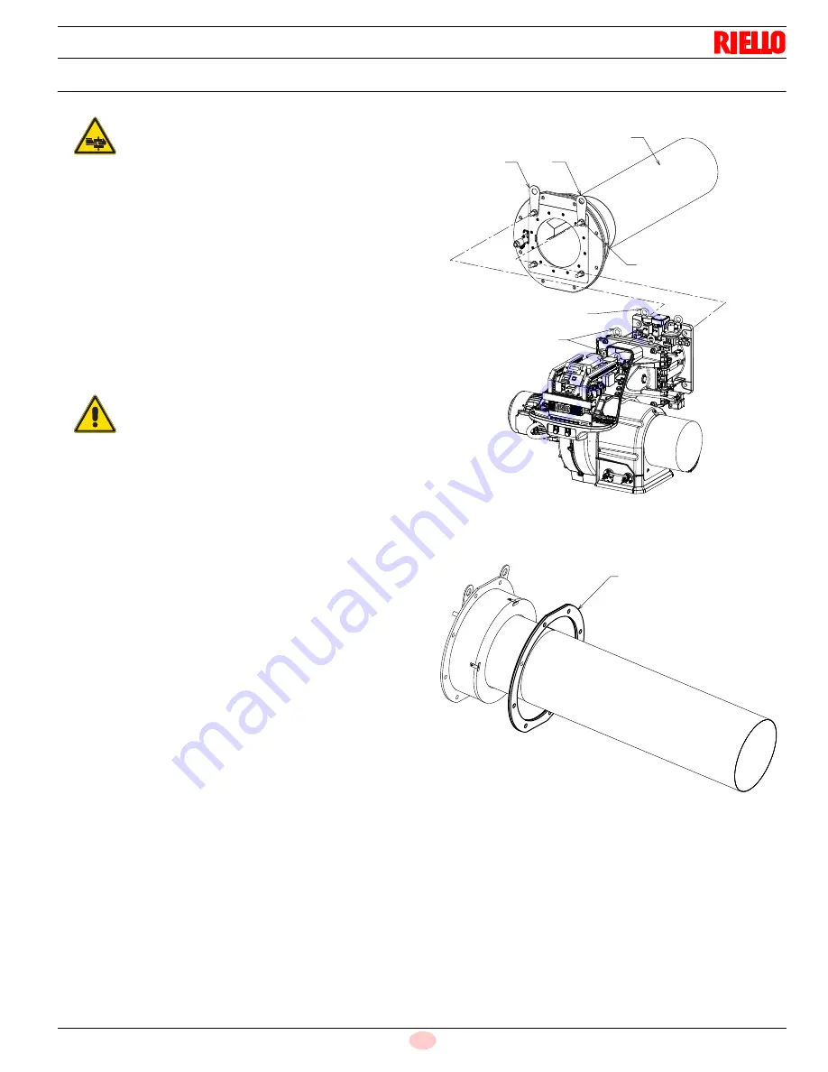
Prepare a suitable lifting system using the rings 3)(Fig. 12) of
the head assembly.
Check
the
correct
positioning
of
the
insulating
gasket 6)(Fig. 13); the black side must be faced the burner
flange and the white one to the boiler side.
Insert the head assembly on the previously prepared boiler
hole (Fig. 12) and fix with the M18 screws.
Remove the rings 3) from the head assembly 1).
Lift the burner by means of the rings 3)(Fig. 12) after having
removed the cover 8) fixing screws 7)(Fig. 12).
Fix the burner onto the head assembly with the supplied
screws 5)(Fig. 12).
After the start-up, check there is no leakage of flue gases into
the external environment.
Prepare a suitable lifting system using the
rings 3)(Fig. 12), after removing the fixing screws 7)
of the casing 8).
WARNING
The seal between burner and boiler must be air-
tight.
3
1
A
B
3
5
3
3
Fig. 12
20122719
6
Fig. 13
20129398
Summary of Contents for RX 2500 S/E
Page 2: ...Original instructions ...


