Installation
21
20140257
GB
4.9
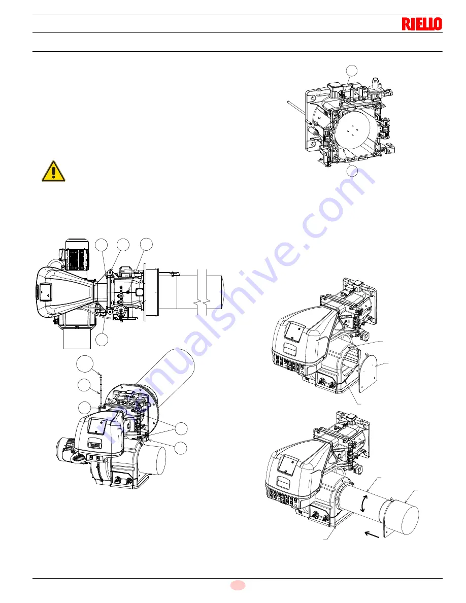
Access to head internal part
The burner leaves the factory set for opening to the left, therefore
maintaining the pin 1)(Fig. 16) in the housing.
To open the burner towards the left, proceed as follows:
A
disconnect the plug/socket 9)(Fig. 16) of the maximum gas
pressure switch;
B
remove the screws 2);
C
open the burner;
D
open the burner fully;
E
undo the screw 4) with pressure test point;
F
release the gas distributor from the seat 5)(Fig. 17) and
remove it.
G Then shift the pin 1) to the opposite side, only then is it possi-
ble to remove the screws 2);
H
Disconnect the socket 9)(Fig. 16) of the maximum gas pres-
sure switch, then proceed as described above at point C).
4.9.1
Filter installation (accessory)
To install the filter kit proceed as follows:
–
loosen the screws 1)(Fig. 18) and remove the screws 2);
–
remove the cover 3).
To remove the filter is necessary:
–
insert the filter 4) inside the burner air intake 6) and rotate
clockwise to fix it;
–
fix the cover 5) with the screws 1) and 2)(Fig. 18).
WARNING
To open the burner from the opposite side, before
removing the pin 1)(Fig. 16), make sure that the 4
screws 2) are tight.
1
2
4
2
10
1
2
2
9
20122819
Fig. 16
4
5
20123545
Fig. 17
1
3
2
4
5
6
20141735
Fig. 18
Summary of Contents for RX 2500 S/E
Page 2: ...Original instructions ...


