background image

Installation

27 

20140257

GB

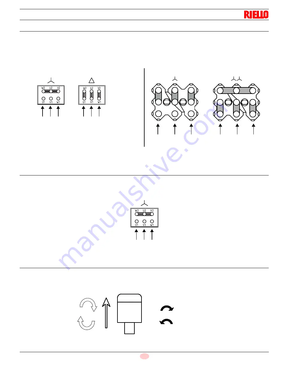
4.15 Motor connection at 208-230 or 460V

WARNING

:

the motors, manufactured for 208-230/460 

IE3/Nema Premium Efficiency

 voltage, have a different connection than 

IE1

 motors, no more

star/delta but 
star/double star. 
Please, pay attention to the indications in case of modification of voltage, maintenance, or substitution.


4.16 Motor connection at 575V

WARNING

:

the motors, manufactured for 575V 

IE3/Nema Premium Efficiency

 voltage, have the same control box base of the IE1 motors. 

Please pay attention to the indications in case of maintenance or substitution.

4.17 Reversible direction

WARNING

:

If it is necessary to reverse the direction then reverse the two main supply phases. 
For example: L1 with L2, there is not difference between 

IE1

 and 

IE3/Nema Premium Efficiency

.

D3686

IE1

IE3/Nema


U2

V2

W2

U3

V3

W3

U1

V1

W1

S8379

U2

V2

W2

U3

V3

W3

U1

V1

W1

S8380

~ ~ ~

~ ~ ~

460V

208-230V

~

~

~

~

~

~

460V

208-230V

Fig. 29

S8382

~ ~ ~

575V

Fig. 30

/ / /

/ / /

VKDIW

S8381

L1

L2

Fig. 31

Summary of Contents for RX 2500 S/E

Page 1: ...nd maintenance instructions Premix gas burners Progressive two stage or modulating operation CODE MODEL 20137777 20137778 RX 2500 S E 20137779 20137780 RX 3000 S E CODE COMBUSTION HEAD ASSEMBLY 20133660 RX 2500 S E 20140481 RX 3000 S E GB ...

Page 2: ...Original instructions ...

Page 3: ...ription 12 3 10 Control box for the air fuel ratio LMV37 4 13 3 11 Actuators SQM33 5 16 4 Installation 17 4 1 Notes on safety for the installation 17 4 2 Handling 17 4 3 Preliminary checks 17 4 4 Operating position 18 4 5 Boiler plate 18 4 6 Head length 18 4 7 Securing the burner to the boiler 19 4 8 Position of electrode flame sensor 20 4 9 Access to head internal part 21 4 9 1 Filter installatio...

Page 4: ... 30 5 6 2 Maximum gas pressure switch 30 5 6 3 Minimum gas pressure switch 30 5 6 4 Air filter pressure switches in case of use of air filter 31 5 7 Flame signal measurement 32 5 8 Final checks with the burner working 32 6 Maintenance 33 6 1 Notes on safety for the maintenance 33 6 2 Maintenance programme 33 6 2 1 Maintenance frequency 33 6 2 2 Safety test with gas ball valve closed 33 6 2 3 Check...

Page 5: ...car ried out correctly may cause damage to the ma chine and or injury to people DANGER DANGER LIVE COMPONENTS This symbol indicates operations which if not car ried out correctly lead to electric shocks with lethal consequences DANGER FLAMMABLE MATERIAL This symbol indicates the presence of flammable materials DANGER BURNING This symbol indicates the risks of burns due to high temperatures DANGER ...

Page 6: ...t of damage to things or injury to peo ple if such damage injury was due to any of the following causes incorrect installation start up use and maintenance of the burner improper incorrect or unreasonable use of the burner intervention of unqualified personnel carrying out of unauthorised modifications on the equipment use of the burner with safety devices that are faulty incorrectly applied and o...

Page 7: ...ance Only those parts envisaged by the manufacturer can be replaced 2 2 Personnel training The user is the person body or company that has acquired the ma chine and intends to use it for the specific purpose He is responsi ble for the machine and for the training of the people working around it The user undertakes to entrust the machine exclusively to suitably trained and qualified personnel under...

Page 8: ...mum delivery 2 natural gas WC 4 2 3 5 Operation Low high or modulating Standard application Boilers water steam thermal oil Ambient temperature F 32 104 0 40 C Combustion air temperature F max 140 60 C Noise levels 3 Sound pressure Sound power dB A 83 1 97 3 83 1 97 3 Model RX 2500 S E RX 3000 S E Control circuit power supply V Ph Hz 120 1 60 Main power supply 10 V Ph Hz 208 230 3 60 460 3 60 575 ...

Page 9: ...rt drawn back on the sliding bars The dimensions of the open burner are indicated by position I Tab E Inch A B C lbs RX 2500 S E 65 41 3 8 49 5 8 308 RX 3000 S E 65 41 3 8 49 5 8 330 D36 Fig 1 WARNING The gas adaptor is set also for DN 80 bore Maximum position for the extraction of the servo motor cover H O O L M P T D N C E R 2 R 1 T x F T z A R R A Fig 2 20122705 Inch P T C D E F L H RX 2500 S E...

Page 10: ...agram WARNING The firing rate value range has been obtained con sidering an ambient temperature of 68 F 20 C and an atmospheric pressure of 394 WC The firing rate areas have been reduced by 10 with respect to the maximum range that can be reached NOx expected emissions on Natural Gas expressed in ppm 3 O2 Riello Burners Sub 30 Sub 20 Sub 9 CO2 O2 CO2 O2 CO2 O2 All models 8 5 8 75 5 8 5 4 8 0 8 5 6...

Page 11: ...bustion chamber Inch ϯ ϱ ϰ Ϭ ϰ ϱ ϱ Ϭ ϱ ϱ ϲ Ϭ ϲ ϱ ϳ Ϭ ϳ ϱ ϴ Ϭ ϴ ϱ ϵ Ϭ ϵ ϱ ϭϬ Ϭ Ϳ EŽdž ф ϯϬ ƉƉŵ EŽdž ф ϮϬ ƉƉŵ Ϭ Ϭ Ϭ ϱ ϭ Ϭ ϭ ϱ Ϯ Ϭ Ϯ ϱ ϯ Ϭ ϯ ϱ Ϭ ϭ ϬϬϬ Ϯ ϬϬϬ ϯ ϬϬϬ ϰ ϬϬϬ ϱ ϬϬϬ ϲ ϬϬϬ ϳ ϬϬϬ ϴ ϬϬϬ ϵ ϬϬϬ ϭϬ ϬϬϬ ϭϭ ϬϬϬ ϭϮ ϬϬϬ EŽdž ф ϵ ƉƉŵ Fig 4 RX 3000 S E Output MBtu h 20140532 ...

Page 12: ...Qburner Qfoc F 4 500 0 908 4 956 Mbtu h AIR TEMPERATURE Altitude Altitude bar press bar press 0 5 10 15 20 25 30 40 C ft a s l m a s l w c mbar 32 41 50 59 68 77 86 104 F 0 0 399 1013 00 1 087 1 068 1 049 1 031 1 013 0 996 0 980 0 948 328 100 394 1000 00 1 073 1 054 1 035 1 017 1 000 0 983 0 967 0 936 1 000 305 385 977 40 1 049 1 030 1 012 0 994 0 977 0 961 0 945 0 915 2 000 610 371 942 80 1 012 0...

Page 13: ...th graduated scale 18 Air pressure switch 19 Pilot gas train 20 Maximum gas pressure switch with pressure test point 21 Sensor 22 Hinge for opening the burner 23 Pressure test point for air pressure switch 24 Combustion head pressure test points 25 Gas train adapter 26 Indication for checking the rotation direction of the purging motor 27 Fixing flange with insulating panel 28 Transparent protecti...

Page 14: ...xiliary circuits fuse includes a spare fuse 11 Air pressure switch 12 Ignition transformer 13 Air filter pressure switch 14 Operator panel with LCD display 15 Light signalling burner lockout 16 Reset button 17 Direct start up line contactor 18 Relay with clean contacts for Warning air filter remote signal terminal board 19 Thermal relay with RESET button 20 Filter pressure switches circuits fuse i...

Page 15: ...cuits via which it is possible to easily identify any causes of malfunctioning Mechanical design The following system components are integrated in the LMV37 4 basic unit Burner control with gas valve proving system Electronic air fuel ratio control Control frequency converter air fan Modbus interface Installation notes Always run high voltage ignition cables separately while ob serving the greates...

Page 16: ...inal voltage Nominal current Power factor AC 120 V 50 60 Hz 1 6 A pilot duty load declaration to UL372 cos 0 4 Alarm output Nominal voltage Nominal current Power factor AC 120 V 50 60 Hz 1 A cos 0 4 Ignition transformer Nominal voltage Nominal current Power factor AC 120 V 50 60 Hz 1 6 A pilot duty load declaration to UL372 or 250 VA ignition load declaration to UL372 cos 0 2 Fuel valves Nominal v...

Page 17: ... T P 10 Shutdown Operation Startup Valve proving OUTPUTS INPUTS Phase number Fuel Actuator 2 Air Actuator 1 Actuators Safety limit thermostat STB Control thermostat or pressurestat R Flame signal FS Air pressure switch LP Pressure switch min Pmin Pressure switch max Pmax Valve proving leakage test P LT POC alternative to Pmax No load position Ignition load Postpurge position Nominal load Low fire ...

Page 18: ...s can be seen on the dis play of the Operator Panel Index 0 for fuel actuator index 1 for air actuator Installation notes Always run the high voltage ignition cables separate from the unit and other cables while observing the greatest possible dis tance The holding torque is reduced when the actuator is disconnect ed from power Technical data Tab H WARNING To avoid injury to persons damage to prop...

Page 19: ...ble means of handling Check also that the area in which you are working is empty and that there is an adequate escape area i e a free safe area to which you can quickly move if the burner should fall During the handling keep the load at not more than 20 25 cm from the ground CAUTION After positioning the burner near the installation point correctly dispose of all residual packaging separating the ...

Page 20: ...gned to operate only in posi tions 1 2 3 and 4 Fig 10 Installation 1 is preferable as it is the only one that allows the maintenance operations as described in this manual Installations 2 3 and 4 permit operation but make maintenance and inspection of the com bustion head more difficult DANGER Any other position could compromise the cor rect operation of the appliance Installation 5 is prohibited ...

Page 21: ...g 12 and fix with the M18 screws Remove the rings 3 from the head assembly 1 Lift the burner by means of the rings 3 Fig 12 after having removed the cover 8 fixing screws 7 Fig 12 Fix the burner onto the head assembly with the supplied screws 5 Fig 12 After the start up check there is no leakage of flue gases into the external environment Prepare a suitable lifting system using the rings 3 Fig 12 ...

Page 22: ...Fig 15 This is fixed on an adaptor 2 with glass 3 and gasket 4 The pipe 5 allows to cool the fixing area of the sensor Check the seal of the plate 6 Fig 15 WARNING Check that the electrode is positioned as in Fig 14 respecting the indicated dimensions 229 2 2 8 2 1 3 5 20151686 Fig 14 1 2 3 4 6 5 20122873 Fig 15 ...

Page 23: ...to the opposite side only then is it possi ble to remove the screws 2 H Disconnect the socket 9 Fig 16 of the maximum gas pres sure switch then proceed as described above at point C 4 9 1 Filter installation accessory To install the filter kit proceed as follows loosen the screws 1 Fig 18 and remove the screws 2 remove the cover 3 To remove the filter is necessary insert the filter 4 inside the bu...

Page 24: ...20140257 22 GB Installation 4 10 Gas butterfly valve If necessary replace the gas butterfly valve The correct position is shown in Fig 19 20078516 Fig 19 ...

Page 25: ... The gas solenoids must be as close as possible to the burner to ensure that the gas reaches the combustion head within the safety time of 3s Ensure that the maximum pressure necessary for the burner is included in the calibration field of the pressure regulator col our of the spring Explosion danger due to fuel leaks in the presence of a flammable source Precautions avoid knocking attrition spark...

Page 26: ...d the corresponding output on the left Example for RX 2500 with natural gas Maximum output operation Gas pressure at test point 1 Fig 22 4 WC Pressure in combustion chamber 1 WC 4 1 3 WC A maximum output of 9 000 Btu hr shown in corresponds to 3 WC pressure This value serves as a rough guide the effective delivery must be measured at the gas meter Tab K MBtu hr p1 WC p2 WC RX 2500 S E 3 400 0 4 0 ...

Page 27: ...to that shown on the identification label and in this manual Do not invert the neutral with the phase in the electrical supply line Any inversion would cause a lockout due to firing failure The electrical safety of the device is obtained only when it is correctly connected to an efficient earthing system made according to current standards It is necessary to check this fundamental safety requireme...

Page 28: ...or is a nominal value To reset in the case of an intervention of the thermal relay press the button RESET Fig 24 The button STOP Fig 24 opens the NC 95 96 contact and stops the motor To test the thermal relay insert a screwdriver in the window TEST Fig 25 and move it in the sense of the arrow towards right 4 14 2 Electronic thermal relay To reset in the case of an intervention of the thermal relay...

Page 29: ...RNING the motors manufactured for 575V IE3 Nema Premium Efficiency voltage have the same control box base of the IE1 motors Please pay attention to the indications in case of maintenance or substitution 4 17 Reversible direction WARNING If it is necessary to reverse the direction then reverse the two main supply phases For example L1 with L2 there is not difference between IE1 and IE3 Nema Premium...

Page 30: ...ant To set the pilot without main burner operation proceed as follows Un programmed unit OFF Upr When appears P0 flashing in the display set air actuator between 0 to 20 Set the pilot pressure Programmed unit OFF Set parameter 208 Program stop to 3 Interval 1 Ph44 With the burner in the manual position set air actuator between 0 to 20 Set the pilot pressure When the setting is correct set paramete...

Page 31: ...several generators in parallel The system includes the following basic functions air and fuels are supplied in correct quantities by positioning the valves by direct servo control thus avoiding the possibility of play typical of systems used for traditional modulating burn ers in which settings are obtained by levers and a mechanical cam burner power is modulated according to the load required by ...

Page 32: ...until the burner locks out Then turn the knob counter clockwise about 20 of the set point and start up the burner again to ensure the set point is correct If the burner locks out again turn the knob counter clockwise a little bit more 5 6 2 Maximum gas pressure switch Adjust the maximum gas pressure switch Fig 36 after having per formed all other burner adjustments with the maximum gas pres sure s...

Page 33: ...librated with two different thresholds The value set on the Warning air pressure switch must be higher than that of the Safety Adjust the filter air pressure switches Fig 38 after performing all other burner adjustments with the air pressure switches set to the start of the scale Connect the pressure gauge as in Fig 35 on page 30 With the burner operating at maximum output insert a combustion anal...

Page 34: ... the right the flame s intensity is displayed as a percentage Example 954 0 0 5 8 Final checks with the burner working Tab L S8171 P V h min s Fig 39 Open the control limit operation Open the high limit operation The burner must stop Rotate the maximum gas pressure switch knob to the mini mum end of scale position Rotate the air pressure switch knob to the maximum end of scale position The burner ...

Page 35: ...s are equipped with light sig nals or close open position indicator that turn on at the same time as their power supply 6 2 3 Checking and cleaning Combustion The optimum calibration of the burner requires an analysis of the flue gases Significant differences with respect to the previous measurements indicate the points where more care should be ex ercised during maintenance Combustion head Open t...

Page 36: ...e indicated in the Tab N Tab N NOx expected emissions on Natural Gas expressed in ppm 3 O2 Riello Burners Sub 30 Sub 20 Sub 9 CO2 O2 CO2 O2 CO2 O2 All models 8 5 8 75 5 8 5 4 8 0 8 5 6 7 5 8 7 25 7 75 8 0 7 1 WARNING The specified life cycles do not refer to the warranty terms indicated in the delivery or payment condi tions Safety component Life cycle Flame control 10 years or 250 000 operation c...

Page 37: ...ss cover 3 from any dust that may have accumu lated pay attention to the seal and thermal insulator 2 WARNING Be extremely careful while troubleshooting the detector line voltage is present on some of the terminals when power is on Open the master switch to disconnect power before removing or installing the detector A 1 2 3 4 Fig 40 20167900 ...

Page 38: ...dix Spare parts A Appendix Spare parts 29 24 42 56 27 19 55 18 4 6 6 21 21 7 16 17 47 20 22 24 26 28 29 30 36 35 34 50 49 44 29 14 43 54 25 28 10 41 48 33 51 52 8 9 59 57 57 60 62 46 57 57 39 40 31 38 32 37 45 32 31 37 38 ...

Page 39: ...969 GAS PRESSURE SWITCH A 21 3007077 SEAL B 22 20073807 HINGE 24 3014011 DISC A 25 20124853 FILTER B 25 20135129 FILTER B 26 3012795 BEARING C 27 20126622 AIR DAMPER ASSEMBLY 28 20008601 SERVOMOTOR B 29 3013937 HUB 30 20075022 JOINT A 31 3012841 BASE 32 20010969 RELAY C 33 20061505 TRANSFORMER B 34 3006155 FAN C 34 20135130 FAN C 35 20036996 MOTOR C 35 20028330 MOTOR C 35 20008598 MOTOR C 35 30141...

Page 40: ...ELECTOR SWITCH 47 3007079 SEAL C 48 20010968 ELECTRONIC CAM C 49 20133154 LEVER ASSEMBLY C 50 3003891 CONNECTOR C 51 3013926 AZL DISPLAY 52 3013940 CONNECTORS ASSEMBLY B 54 20075918 GAS REGULATOR C 55 20075919 TUBE C 56 20075921 VIEWING PORT 57 20036017 GREEN SIGNAL LIGHT A 59 20027020 YELLOW SIGNAL LIGHT A 60 20010962 PUSH BUTTON 62 20027422 SELECTOR SWITCH N COD 20137777 20137778 20137779 201377...

Page 41: ... Spare parts for extended safety fittings 101 102 103 104 108 106 105 107 N COD 20133660 20140481 DESCRIPTION BURNER SERIAL NUMBER 101 20124967 FLANGE GASKET A 102 20167947 COMBUSTION HEAD 102 20167948 COMBUSTION HEAD 103 20124780 SEAL B 104 20155045 FLANGE 105 20124845 FLANGE INSULATION 106 20155042 ELECTRODE A 107 20117111 VIEWING PORT 108 20124851 SEAL B ...

Page 42: ...rain according to UL Standards Filter Filter cover B Appendix Accessories WARNING The installer is responsible for the supply and instal lation of any required safety device s not indicated in this manual Burner Code RX 2500 3000 S E 20141720 ...

Page 43: ...O2 Low Fire High Fire Main Power Supply O2 Low Fire High Fire Control Power Supply CO Low Fire High Fire Burner Firing Rate NOX Low Fire High Fire Manifold Pressure Net Stack Temp Low Fire High Fire Pilot Flame Signal Comb Efficiency Low Fire High Fire Low Fire Flame Signal Overfire Draft High Fire Flame Signal CONTROL SETTINGS Operating Setpoint Low Oil Pressure High Limit Setpoint High Oil Press...

Page 44: ...BURNERS NORTH AMERICA 35 Pond Park Road http www riello ca 2165 Meadowpine Blvd Hingham Massachusetts Mississauga Ontario U S A 02043 1 800 4 RIELLO Canada L5N 6H6 RIELLO S p A I 37045 Legnago VR Tel 39 0442 630111 http www riello com ...

Reviews: