19
GASZULEITUNG
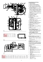
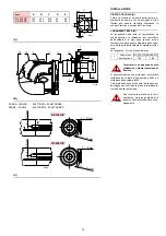
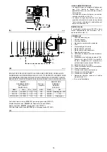
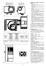
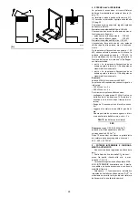
• Gasarmaturen sind über Flansch 2)(A), Dich-
tung 3)(A) und Schrauben 4)(A), zur Brenner-
ausstattung gehörend, mit dem Gasanschluß
1)(A) zu verbinden.
• Die Armatur kann je nach Bedarf von rechts
bzw. links zugeführt werden, s. Abb. (A).
• Die Armatur L der Gaszuleistung muss so nah
wie möglich am Brenner liegen, damit die Gas-
zufuhr zum Flammkopf innerhalb 3 Sekunden
sichergestellt ist.
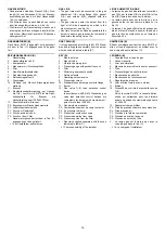
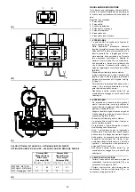
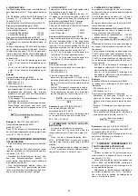
GASARMATUREN (B)
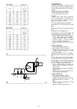
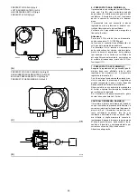
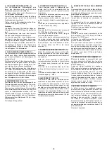
Nach Norm EN 676 typgeprüft, wird gesondert
mit dem in Tab. (C) angegebenen Code gelie-
fert.
ZEICHENERKLÄRUNG (B)
1 - Gaszuleitung
2 - Handbetätigtes Ventil
3 - Kompensator
4 - Manometer mit Druckknopfhahn
5 - Filter
6 - Gas-Minimaldruckwächter
7 - Sicherheitsmagnetventil
8 - Betriebsmagnetventil
9 - Druckregler
10 - Dichtung und Flansch Brennergrundaus-
stattung
11 - Brenner
12 - Dichtheitskontrolleinrichtung der Gasven-
tile 7)-8). Laut Norm EN 676 ist die Dicht-
heitskontrolle für Brenner mit
Höchstleistung über 1200 kW Pflicht.
13 - Passtück Armatur-Brenner
PF - Brennkammer-Druckentnahmestelle
PL - Luftdruckentnahmestelle
P1 - Druck am Flammkopf
P2 - Druck nach dem Ventil
P3 - Druck vor dem Filter
L - Gasarmatur gesondert mit dem in Tab. (C)
angegebenen Code geliefert.
- L1-Vom Installateur auszuführen
GAS LINE
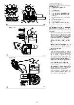
• The gas train must be connected to the gas
attachment 1)(A), using flange 2)(A), gasket
3)(A) and screws 4)(A) supplied with the
burner.
• The gas train can enter the burner from the
right or left side, depending on which is the
most convenient, see fig. (A).
• Gas train L must be as close as possible to the
burner to ensure gas reaches the combustion
head within the safety time of 3 s.
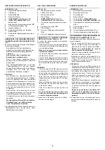
GAS TRAIN (B)
It is type-approved according to EN 676 Stand-
ards and is supplied separately from the burner
with the code indicated in table (C).
KEY (B)
1 - Gas input pipe
2 - Manual valve
3 - Vibration damping joint
4 - Pressure gauge with pushbutton cock
5 - Filter
6 - Minimum gas pressure switch
7 - Safety solenoid
8 - Operating solenoid valve
9 - Pressure governor
10 - Standard issue burner gasket with flange
11 - Burner
12 - Gas valve 7)-8) leak detection control
device.
In accordance with EN 676 Standards, gas
valve leak detection control devices are
compulsory for burners with maximum out-
puts of more than 1200 kW.
13 - Gas train/burner adaptor
PF - Combustion chamber pressure test point
PL - Air pressure test point
P1 - Pressure at combustion head
P2 - Pressure downline from valve
P3 - Pressure up-line from the filter
L - Gas train supplied separately with the code
indicated in table (C)
- L1-The responsibility of the installer
LIGNE ALIMENTATION GAZ
• La rampe du gaz doit être reliée au raccord du
gaz 1)(A), par la bride 2)(A), le joint 3)(A) et les
vis 4)(A) fournis de série avec le brûleur.
• La rampe peut arriver par la droite ou par la
gauche selon les cas, comme indiqué sur la
fig. (A).
• La rampe L du gaz doit être le plus près possi-
ble du brûleur de façon à assurer l’arrivée du
gaz à la tête de combustion en un temps de
sécurité de 3 s.
RAMPE GAZ (B)
Elle est homologuée suivant la norme EN 676 et
elle est fournie séparément du brûleur avec le
code indiqué dans le tableau (C).
LEGENDA (B)
1 - Canalisation d’arrivée du gaz
2 - Vanne manuelle
3 - Joint anti-vibrations
4 - Manomètre avec robinet à bouton poussoir
5 - Filtre
6 - Pressostat gaz de seuil minimum
7 - Electrovanne de sécurité
8 - Électrovanne de fonctionnement
9 - Régulateur de pression
10 - Joint et bride fournis avec le brûleur
11 - Brûleur
12 - Dispositif de contrôle d’étanchéité vannes
7)-8).
Selon la norme EN 676, le contrôle d’étan-
chéité est obligatoire pour les brûleurs
ayant une puissance maximale supérieure
à 1200 kW.
13 - Adaptateur rampe-brûleur
PF - Prise de pression chambre de combustion
PL - Prise pression air
P1 - Pression à la tête de combustion
P2 - Pression en aval de la vanne
P3 - Pression en amont du filtre
L - La rampe gaz est fournie à part avec le
code indiqué dans le tab. (C)
- L1-A la charge de l’installateur
-
Summary of Contents for RX 350 S/P
Page 2: ......
Page 49: ...43 0 1 2 3 3 3 4 3 5 3 3 3 3 3 3 3 3 3 3 4 3 RX 350 S P...
Page 50: ...44 0 1 1 1 2 1 3 1 1 1 1 1 1 1 1 1 1 2 1 445 RX 500 S P...
Page 53: ...47 0 0 0 1 0 2 0 0 0 0 0 0 0 0 0 0 1 0 RX 350 S P...
Page 54: ...48 0 0 0 1 0 2 0 0 0 0 0 0 0 0 0 0 1 0 RX 500 S P...
Page 55: ...49 0 0 1 2 3 45 6 6 67 8 8 0 8 8 9 8 6 6 6 6 6 6 6...
Page 61: ......
Page 62: ......
Page 63: ......

