20151717
14
GB
Technical description of the burner
Installation notes
Arrange the high voltage ignition cables separately, as far as
possible from the control box and the other cables.
Do not confuse the powered conductors with the neutral
ones.
Install the switches, fuses and grounding in compliance with
local regulations.
The connection diagrams show the burner controls with
grounded neutral conductor.
Make sure that the maximum admissible current of the termi-
nal connections is not exceeded.
Make sure the cable grommets of the connected cables
comply with the relevant standards.
Do not supply mains voltage to the control box outputs. Dur-
ing the testing of the devices controlled from the burner con-
trol (fuel valve, etc), the LME71… should not be connected
to the units.
The mechanical connection between the actuators and the
fuel and air control elements, or any other type, should be
rigid.
Make sure there are no short-circuits on the air pressure
switch connection lines.
Electrical wiring to the flame detectors
It is important for signal transmission to be practically free of any
disturbances or loss:
Always separate the detector cables from the other cables:
– the capacitive reactance of the line reduces the magnitude
of the flame signal;
– use a separate cable.
Respect the permitted lengths for the cables of the detectors
(see Technical Data).
The ionisation probe powered from the mains is not pro-
tected from the risk of electric shocks.
Position the ignition electrode and the ionisation probe so
that the ignition spark cannot form an arc on the probe (risk
of electric overload) and that it cannot negatively effect the
supervision of the ionisation.
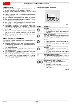
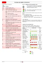
Description of displays and buttons
Tab. F
Button
Function
Button A
–
Displaying default output
–
In lockout position: output value at the time of
the fault
Enter and Info button
The reset button (info button) is the key element
for resetting the burner control and activating/de-
activating the diagnostic functions.
Button -
–
Displaying flame 2 signal current or display-
ing phases
–
In lockout position: MMI phase at the time of
the fault
–
Displaying flame 1 signal current or display-
ing phases
–
In lockout position: MMI phase at the time of
the fault
Warning light with 3 colours
The warning light with three colours (red - yellow
- green) is the key indicator of the visual diagnos-
tics.
and -: escape function
Press the + and - buttons at the same time!
–
No adoption of value
–
Access to a higher menu level
–
Keep pressed for >1 second for the backup/
reset function
nfo
+
-
A
S8595
Fig. 7
A
nfo
-
+
-
+
and
Summary of Contents for RX 360 S/PV
Page 2: ...Translation of the original instructions...
Page 68: ...20151717 63 Appendix 0 0 0 1 0 2 0 0 0 0 0 0 0 0 0 0 1 0...
Page 69: ...64 20151717 Appendix...
Page 70: ...20151717 65 Appendix 0 1 1 1 1 1 1...
Page 71: ...66 20151717 Appendix 0 0 0 1 1 2 3 435678...
Page 75: ......


