15
20151717
GB
Technical description of the burner
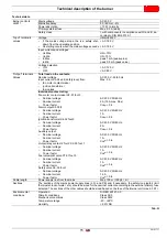
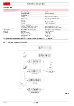
Technical data
Tab. G
Burner controls
LME71...
Mains voltage
AC 230 V
Mains frequency
50 / 60 Hz +- 6%
Power absorption
<10 W, normally
Primary external fuse
Max. 6.3 A (slow)
Safety class
I, with components in compliance with II and III, ac-
cording to DIN EN 60730-1
“Input” terminals
values
Voltage
UMains 230 V
•
If the mains voltage drops, the is a safety shut-
down from the operating position
•
Restarting occurs when the mains voltage exceeds
< AC 165 V
> AC 195 V
Input currents and voltages
–
UeMax
–
UeMin
–
IeMax
–
IeMin
UN +10%
UN -15%
peak 1 mA (peak value)
peak 0.5 mA (peak value)
Voltage detection
–
ON
–
OFF
> AC 120 V
< AC 80 V
“Output” terminals
Values
Total load on the contacts:
Nominal voltage
Input current X3-04 unit (safety loop) from:
–
fan motor contact maker
–
ignition transformer
–
fuel valves
AC 230 V - 50/60 Hz
Max. 5 A
Individual contact rating:
Fan motor contact maker X2-01 foot 3
–
Nominal voltage
–
Nominal current
–
Power factor
AC 230 V 50/60 Hz
2 A (15A max. 0.5 s)
Cos
0.4
Alarm output X2-03/3
–
Nominal voltage
–
Nominal current
–
Power factor
AC 230 V 50/60 Hz
1A
Cos
> 0.6
Ignition transformer X4-02 foot 3
–
Nominal voltage
–
Nominal current
–
Power factor
AC 230 V 50/60 Hz
2A
Cos
> 0.4
Auxiliary output
–
Nominal voltage
–
Nominal current
–
Power factor
AC 230 V 50/60 Hz
1A
Cos
> 0.6
Output relay contact 2 foot 2 X2-09 foot 7
–
Nominal voltage
–
Nominal current
–
Power factor
AC 230 V 50/60 Hz
1A
Cos
> 0.4
Fuel valve/pilot valve X7-01 foot 3
–
Nominal voltage
–
Nominal current
–
Power factor
AC 230 V 50/60 Hz
1A
Cos
> 0.4
Safety valve X6-03 foot 3
–
Nominal voltage
–
Nominal current
–
Power factor
AC 230 V 50/60 Hz
1.5 A
Cos
> 0.6
Cable length
Power supply line from the mains
Max. 100 m (100 pF / m)
Sections
The sections of the mains power supply lines (L, N, and PE) and, if necessary, the safety loop (safety limit
thermostat, lack of water, etc.) should be sized for the nominal currents according to the external primary fuse
selected. The sections of the other cables should be sized based on the fuse of the internal unit (max. 6.3 AT).
Environmental
conditions
Operation
Climatic conditions
Mechanical conditions
Temperature range
Humidity
DIN EN 60721-3-3
Class 3K3
Class 3M2
-40...+60°C
< 95% RH
Summary of Contents for RX 360 S/PV
Page 2: ...Translation of the original instructions...
Page 68: ...20151717 63 Appendix 0 0 0 1 0 2 0 0 0 0 0 0 0 0 0 0 1 0...
Page 69: ...64 20151717 Appendix...
Page 70: ...20151717 65 Appendix 0 1 1 1 1 1 1...
Page 71: ...66 20151717 Appendix 0 0 0 1 1 2 3 435678...
Page 75: ......


