17
20151717
GB
Technical description of the burner
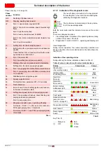
Tab. H
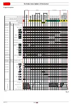
Times
Tab. I
AL
Alarm device
AUX
Auxiliary output
Dbr
Lead connection
Reset button (info button)
EK2
Remote reset button
FSV
Flame signal amplifier
ION
Ionisation probe
K...
Relay contact
LED
Warning lamp with 3 colours
LP
Air pressure switch
LR
Load controller
LR-OPEN
Load controller OPEN
LR-CLOSE
Load controller CLOSED
M
Fan motor
NT
Power supply unit
P LT
Pressure switch valve test
Pmax
Max. pressure switch
Pmin
Min. pressure switch
POC
Closure test
PV
Pilot valve
QRA...
UV flame detector
R
Control thermostat or pressure switch
SA
Actuator
SA-KL
Low flame actuator
SA-NL
High flame actuator
SA-R
Feedback actuator
SA-Z
Actuator CLOSED
SA-ZL
Ignition load actuator
SL
Safety loop
STB
Safety limit thermostat
SV
Safety valve
V1
Fuel valve
V2
Fuel valve
V2a
Fuel valve
W
Limit pressure switch or thermostat
Z
Ignition transformer
µC
µC controller
Input/output 1 signal (ON)
Input/output 2 signal (ON)
Input 1 permitted signal (ON) or 0 (OFF)
/reset
(EK1)
TSA
Safety time
tw
Waiting time
t1
Pre-purge time
t3
Pre-ignition time
t3n
Post-ignition time (P257 +0.3 seconds)
Ignition time
6s
pilot valve ON - fuel valve OFF
6÷12s
pilot valve ON - fuel valve ON
>12s
pilot valve OFF - fuel valve ON
t4
Interval: end of safety time load controller
release
t8
Post-purge time
t10
Specified time air pressure switch state mes-
sage (time out)
t11
Opening time of actuator (time out)
t12
Closing time of actuator (time out)
Summary of Contents for RX 360 S/PV
Page 2: ...Translation of the original instructions...
Page 68: ...20151717 63 Appendix 0 0 0 1 0 2 0 0 0 0 0 0 0 0 0 0 1 0...
Page 69: ...64 20151717 Appendix...
Page 70: ...20151717 65 Appendix 0 1 1 1 1 1 1...
Page 71: ...66 20151717 Appendix 0 0 0 1 1 2 3 435678...
Page 75: ......


