20151717
22
GB
Installation
5.7
Securing the burner to the boiler
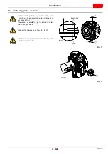
In order to fix the burner to the boiler, proceed as follows:
Assemble the air intake 1) with the screws 2) and nuts.
Connect the high voltage cables to the transformer
3)(Fig. 15), and the ionisation probe lead to the appropriate
cable emerging from the control box.
Fix the gas train unit 4)(Fig. 15) and the gas pipe (5) with the
screws, nuts and the washers supplied as standard equip-
ment. Interpose the gaskets (7) as in Fig. 15.
Assemble the pilot train supplied as standard 6)(Fig. 15).
Check that the sealing ogive is inside the connector 8).
Insert the pilot train 6)(Fig. 15) on connector 8) and tighten
the nut fully home.
Install the gas train following the instructions on pag. 24.
Screw the studs 2)(Fig. 16) onto the boiler plate 1).
Position the refractory gasket 3).
Position the silicone rubber gasket 4).
Fix the flange of the burner (Fig. 16) to the boiler plate and
tighten the nuts 5)(Fig. 16).
DANGER
All the installation, maintenance and disassembly
operations must be carried out with the electricity
supply disconnected.
Provide an adequate lifting system.
WARNING
The seal between burner and boiler must be air-
tight.
WARNING
Be aware of the presence of the gasket 7)(Fig. 15)
and the gas seal.
WARNING
Use a suitable sealant and check the general gas
seal during operation, in particular with respect to
tube 5)(Fig. 15).
WARNING
During this operation, take care not to touch the
electrode unit.
Fig. 15
2
1
4
3
7
5
7
6
8
20130152
1
2
3
4
5
6
Fig. 16
D8666
Summary of Contents for RX 360 S/PV
Page 2: ...Translation of the original instructions...
Page 68: ...20151717 63 Appendix 0 0 0 1 0 2 0 0 0 0 0 0 0 0 0 0 1 0...
Page 69: ...64 20151717 Appendix...
Page 70: ...20151717 65 Appendix 0 1 1 1 1 1 1...
Page 71: ...66 20151717 Appendix 0 0 0 1 1 2 3 435678...
Page 75: ......


