38
INSTALLER
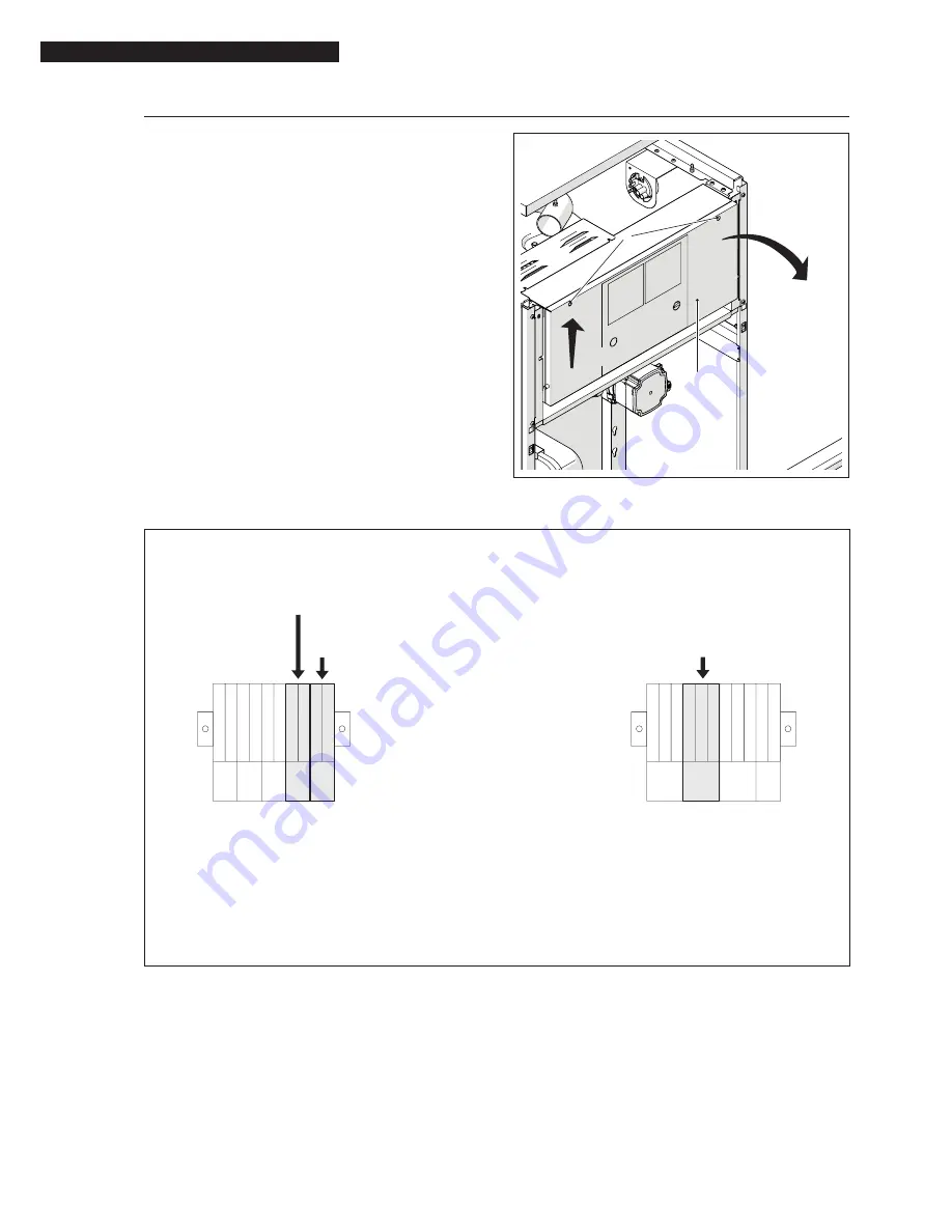
ROTATE
LIFT
5
2
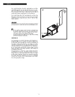
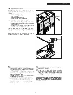
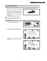
Proceed as follows to access the control panel terminal
strip.
− Unscrew the screws (5) and rotate the control pa-
nel (2) outwards
− Route the connection cables through the cable
grommets in the rear of the control panel and
the slots inside the front of the panel.
Once you have made all the necessary connections,
close the control panel, reversing the steps followed to
open it.
2 .15
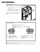
Sensor connections
12 13 14 15 16 17 18 19 20 21
+ - + - + - + - + -
PWM SM SR SB
SE
STORAGE CYLINDER PUMP
Terminals 4-5-6
OUTDOOR TEMPERATURE SENSOR (supplied)
Terminals 20-21
STORAGE CYLINDER TEMPERATURE SENSOR (accessory)
Terminals 18-19
1 2 3 4 5 6 7 8 9 10 11
PE N L1 PE N L1
N L1
PE N L1
T. reg.
PB
PI 1
ALARM
The control panel terminal strip
9
If a storage cylinder is present, the storage cylinder temperature sensor must be located according to the instruc-
tions provided with the storage cylinder.
9
For information on how to connect up additional kits, refer to the instructions provided with the kits themselves.
SM
CH flow temperature sensor
SR
CH return temperature sensor
SB
Storage cylinder temperature sensor
(accessory)
SE
Outdoor temperature sensor (supplied)
T.reg Connection for temperature controller (accessory)
PB
Storage cylinder pump
PI1
CH pump
ALARM 230 Vac output for burner lockout indicator
PWM Not available

