1 General Information
1.1 Security wireless inertia detector «GRAN-RK» (hereinafter «the Detector»)
is designed to detect changing of the monitored item position from it’s its
initial installation place and sending an alarm messages via wireless two-way
communication within frequency range from 433,05 to 434,79 MHz by the
«RIELTA Contact-R» protocol.
1.2 The Detector is designed for operation as a component of a system, that
is operated by a control panel (hereinafter «CP») supporting «RIELTA Contact-R»
wireless two-way communication protocol.
1.3 The Detector generates no interferences to other types of detectors, as
well as to domestic radio equipment.
1.4 The detector is powered by two power-supply batteries СR2450 type: main
and back-up one, both inside the Detector case.
1.5 The Detector generates and transfers messages with the following
information content:
- «Normal» – under keeping initial position;
- «Tilt-Alarm» – under tilt changing for 3° or more;
- «Displacement-Alarm» – item displacement from its initial position at a distance
0.25 m or more with the acceleration of 0.5 m/s
2
and more along any axis during
the period at least 1 s;
- «Tamper» – under case tampering or the detector removal from its place
of installation;
- «Failure» – under long-term vibration interferences;
- «Main power-supply low-battery» – main power-supply battery voltage drop
for less than 2.4 V;
- «Backup power-supply low-battery» – back-up power-supply battery voltage
drop for less than 2.4 V;
1.6 Wireless two-way communication «Detector – CP», is provided at the main
or reserve frequencies. Switching between the main and reserve frequencies is
accomplished automatically.
1.7 The detector provides immunity to electromagnetic interferences.
1.8 Industrial interferences created by the Detector does not exceed the
limits for the facilities used in housing, commercial zones or production areas
with low power consumption.
1.9 The Detector is designed for continuous and uninterrupted operation.
1.10 The Detector operational stability provides its normal operation under
the following influencing factors:
a) Tilt changing for at least 1°,
b) Displacement from its initial position for the distance not more than 0.1 m
with the acceleration of 0.2 m/s
2
and more along any axis during the period
at least 1 s.
1.11 The Detector provides a possibility of a tilt sensitivity adjustment (the
sensitivity value is adjusted as one of a number of: 3°, 10°, 25°, 45°), as well as
displacement threshold adjustment (displacement threshold is adjusted as one
of a number of: 1 – min, 2, 3, 4, 5, 6, 7, 8 – max).
2 Specifications
Table 1
Parameter Name
Value
Power supply
2,6 V … 3,8 V DC
Operating temperature
minus 10 … +50 °С
Permissible relative humidity at +35 °С without moisture
condensation
95 %
Dimensions, max
65х55х20 mm
Weight, max
0,05 kg
IP rating
IP54
Mean time to failure, not less
60 000 hours
Average service life
8 years
Battery life, up to
12 months
3 Scope of Delivery
Each Detector unit package contains the items listed in Table 1.
Table 2
Description
Quantity
Security wireless inertia detector «GRAN-RK»
1 pc.
Lithium power-supply battery СR2450
2 pc.
Screw 3-3х30.016
1 pc.
The Detector Installation Guide
1 copy
4 The Detector Design
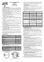
The Detector layout is shown in Fig.1.
SECURITY WIRELESS INERTIA
DETECTOR
«GRAN-RK»
Installation Guide
The Detector comprises the following elements: the base with an openable
fixing hole (6) and a case cover with the printed circuit board (PCB) installed (1).
Main power-supply battery holder (2), «Reset» contacts (3), backup power-
supply battery holder (4), tamper (5) are located on the PCB.
5 Led indication
The Detector generated the following LED indication types:
- LED indication of the mode «Binding» (procedure of the Detector logging
in the CP);
- LED indication of the mode «Identification» is switched ON by the relevant
command from the CP;
- the LED indication continues lighting during 15 minutes after the case is
closed if other types of indication are OFF, and «Tamper» message or indication
inhibition command from the CP are not generated.
The LED indication modes are listed in Table 3.
Table 3
The Detector Mode
LED indication
Note
Binding procedure finishing
LED lighting red for 2-3 s
«Identification»
Alternate Red and green LED
lighting
«Identification» indication
Alternate LED blinking red
and green
by the relevant command
from the CP
«Tilt-Alarm»*
«Displacement-Alarm»*
LED blinking red every 4 s
until the relevant messages
delivery is conformed
«State» indication is
ON, «Identification»
indication is OFF
«Communication Quality»
See section «Communication Quality Appraising»
«Interference»* indication
LED blinking green with
the frequency 5 Hz under
detection of a movement with
acceleration of 0.2 m/s and
more
«State» indication is
ON, «Identification»
indication is OFF
Initial orientation storage
procedure finishing
LED lighting green for 2-3 s
«State» indication is
ON, «Identification»
indication is OFF
«Norm»
Indication is OFF
*) – The LED indication of the Detector
6 Binding with the CP
The binding procedure is intended for logging of the Detector in the CP with
further service information exchange.
6.1 Prepare CP for binding according to the CP Installation Guide.
6.2 After completing sect. 6.1, install the backup power-supply battery to the
backup power-supply battery holder (4) and then the main one to the holder (2).
6.3 Alternate LED blinking green indicates that the Detector is in «Binding»
mode.
6.4 In case of the absence of the indication mentioned above, close the
contacts «Reset» for 2-3 s.
6.5 Successful binding procedure finish is displayed by the Led indicator
lighting red for 2-3 s.
6.6 The time of binding procedure fulfillment is limited to 100 s, after it the
Detector switches to a sleeping mode. For «Binding» mode resumption it is
necessary to close the contacts «Reset» for 2-3 s.
7 Operating Modes
The Detector provides two operating modes – Mode 1 and Mode 2.
7.1 At Mode 1 the initial orientation in the space is stored after each «Tilt-
Alarm» and «Displacement-Alarm» message generation.
7.2 At Mode 2 the initial orientation in the space is stored after closing the
case of the Detector.
The «Norm» mode resumption after «Tilt-Alarm» message generation is fulfilled
only after the Detector initial position is restored.
7.3 The Detector operating mode is defined by the state of case tamper con-
tacts during initial 2 seconds after the successful binding procedure finishing
or during initial 2 seconds after energizing of the Detector logged in the CP. If
the tamper contact is closed, the Detector switches to Mode 1; if the tamper
contact is opened, the Detector switches to Mode 2.
7.4 To finish the Detector initial position storage procedure, it is necessary to
ensure its immobility for the time not less than 5 s. The successful finish of the
storage procedure is displayed by generation of «Norm» message and repeated
by the correspondent LED indication (See table 3).
8 Availability Check
8.1 To check the Detector availability it is necessary to:
- put the base on the flat surface;
- set the cover with the PCB on the base and leave it fixed for 8-10 s.
8.2 After getting the regular «Norm» message, the Detector should be displaced
for 25-30 cm or tilted for 3° or more. After detecting change of its initial position,
the Detector should transmit the message «Tilt-Alarm» or «Displacement-Alarm» and
repeat it by red LED indicator, located on the PCB (See Table 3).
9 Communication Quality Appraising
9.1 In order to check the wireless communication availability, accomplish the
following steps:
- set at first the back-up power-supply battery, than the main one to the holders;
- place the Detector to the assumed place of mounting;
- push and release The Detector tamper contact.
9.2 After tamper contact release, the Detector generates «Tamper» message and
transmits it via radio communication channel. The message is followed by the LED
indication, displaying the radio communication quality in accordance with Table 4.
а) Base
b) Cover with the circuit board installed
1
6
2
3
4
5
BACKUP
MAIN
RESET
Figure 1


