FAN SPEED CONTROL ADR 80 - 230
ADR80230_5.04_eng
Project:
ADR Regulator
Revision Doc.:5,0
Date
: 29.05.2009
Page.
7
Setup
in ADR
Min
10 %
Max
85 %
Start
at 12.5 bar
End
at 20.0 Bar
SET
17 bar
Prop.-
band
2.5 bar
Note: Do not use a small proportional band otherwise you may expect hunting
Based on the setup above following control will be in function
Band in which you find a definite speed regulation
Start
Start of
prop.-band
Proportional-
band
SET Proportional-
band
End of
Prop.-Band
Full
Speed
Pressure bar
12.5
14.5
2.5
17.0
2.5
19.5
20.0
Temperature °C
>35.0
40°
40°- 46°
46°
46° - 52°
52°
53°
Voltage (output) in %
10
10
= 85%
100 %
6.4.0 To control two different Set points and how to define = DUO SET
The firmware in the EEPROM allows the usage of two different Set points. This with one sensor, with two of a kind or differ-
ent sensors (i.e. Temperature sensor and pressure transducer).
.
6.4.1 Window to set „DUO SET“
After your decision to use 2 sensors (Probes) follow option are open to be set.
Example: Pressure
Example input control parameter for DUO - SET
As before you can configure the control parameter for each Sensor in the subdirectory “REGULATION”
6.4.2 Sensors/Pressure transducer 1 or 2 Set points (DUO-SET)
Each sensor input can be defined separate according to the different Probes (Example)
Sensor 1 (P1)or (S1): Pressure via pressure transmitter, Sensor 2 (P2) or(S2): Temperature via temperature sensors NTC
Attention: Do not forget to place the correct jumper according to the sensor
6.
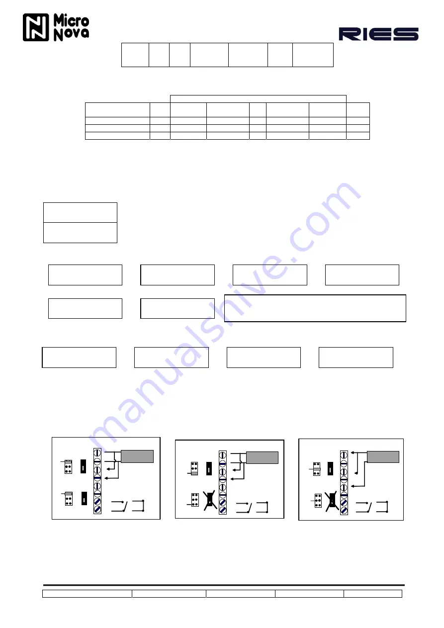
4.3 Wiring and placing jumpers for 2 set point but one sensor only
Attention: Bypass connection has to be made potential free (no voltage)
Depending to the sensor input Jumper have to be placed. Please consider for 1 sensor with 2 set points with open Bypass (SET1) control is fixed by set point S1.
With closed Bypass (SET2) control is taken over by set point 2
Î
PROBES FUNCtion
NORMAL
Ú
Î
P1
PROBE TYPE:
CURR 4 20 mA
Ú
Î
P1
MAX PRESSURE
IN BAR 30.0
Ú
Î
P1
REGULATION
PRESSURE
Ú
Î
P1
INPUT REG
IN BAR
Ú
Î
P1
FREON TYPE
FREON R22
Ú
Î
P1
WORKING IN
CHILLER
Ú
Î
P1
REGULATION
START 9.5 BAR
Ú
Î
P1
REGULATION
STOP 20.0 BAR
Ú
Î
P1 REGULATION
SET 17.0 BAR
Ú
Î
P1 REGULATION
BAND 2.0 BAR
Ú
V
JP1 (IN1)
V
JP2 (IN2)
IN1
IN
+12
GND
BY PASS
+
+
-
-
0 - 10 V
SET 1
SET 2
V
I
N
V
I
N
JP1 (IN1)
JP2 (IN2)
+12
GND
BY PASS
NTC - 10K
NTC
NTC
IN1
IN2
+
+
-
-
SET 1
SET 2
NO
V
I
N
V
I
N
mA
JP1 (IN1)
mA
JP2 (IN2)
+12
GND
BY PASS
0-20 / 4-20 mA
IN1
IN2
SET 1
SET 2
NO
V
I
N
V
I
N
+
-
-
Î
PROBES FUNCtion
INDEPENDANT
Ú
NORMAL
A „normal“control between both sensors
will take place. In function “Chiller” the
highest value of both sensor will control the
output of the ADR. In function “Heatpump”
the lowest value of both sensors controls
the output.
INDEPENDANT
The firmware offers for each sensor a
window for an individual programming of
each probe. No o matter if it is for tempera-
ture , pressure, external voltage or chiller
and heatpump
Same windows also available for Sensor (Probes)2
P1 = Sensor 1, P2 = Snesor 2


