Page 14
S
15
S
31
S
15
S
16
27
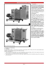
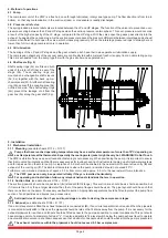
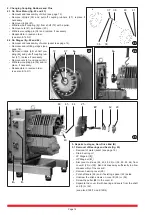
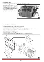
6. Changing Blades (fig. 27)
• Removal of water jacket and non-drive end B of compressor stage (see page 12 and 13)
• Withdraw blades (S
31
) and examine.
• Important! If required, replace blades only in
sets.
• Insert blades in rotor slots (the bevelled side
of the blades have to be at the rotor surface).
• Slightly oil blades before assembly. Blades
should move easily in rotor slots.
• Re-assembly of non-drive end B of compres-
sor stage and water jacket (see page 12 and
13).
7. Repairs to stages, Drive End A
• HP and LP stages are constructed similarly.
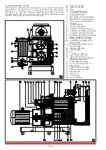
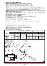
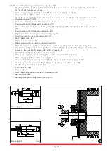
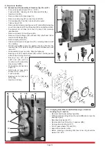
7.1 Removal of Bearings and Seals (see fig. 28 and E 165/1, E 165/4)
• Removal of water jacket and compressor stage (see page 12).
• Disconnect oil lines on end cover A (8) or (54) and bend oil lines away sufficiently to allow dis-assembly of the cover.
• Remove threaded pin (45) from the coupling (35) and pull coupling from shaft end using a puller.
• Remove screws from bearing cover (22) and remove bearing cover with spacer (7).
• Unscrew plug (98) with sealing ring (99).
• Remove threaded pin (18) with allen key (3 mm).
• Remove screws in the end cover (8) or (54).
• Using a puller, free the end cover with the seals and the outer ring (21) from shaft end (3) or (52).
28
W
1
W
2
W
6
W
5
9
8
1
21
24
23
22
35
16
12
18
98
99
7
45
19
18
14
10
13
12
11
15
20


