background image


-

 21 -

 | 

Page              Rigel Medical 

62353+ 

user Manual V1.4 


Next  step  is  to  save  the  name  of  the  newly  create  Test  Name,  by  pressing  the  OK 

button  (F4).  Pressing  the 

  key  (F3)  would  return  to  the  Test  Sequence  menu 

without changes. 
 
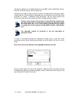
The  newly  created  Test  Name  now  appears  in  the  Test  Sequence  menu  and  can  be 

modified to include the required individual tests. Press the 

 button (F4) to open 

the sequence for editing. 


Once  the  Test  Sequence  has  been  opened,  individual  tests  can  be  inserted  by 
highlighting the place where a new test needs inserting using the up and down keys. 


Note; Tests will be inserted before the highlighted position not after. 


To modify a test sequence, please refer to 2.1.3. 


Summary of Contents for 62353 PLUS

Page 1: ...Innovating Together RIGEL 62353 PLUS electrical safety analyser Copyright 2016 SEAWARD GROUP Last Update 20th April 2016 Instruction Manual 407A556 Revision 1 4...

Page 2: ...tems returned for calibration outside of the 13 month period stated above may not be eligible for the second 12 month section of warranty The second 12 month section of the warranty begins at the expi...

Page 3: ...t from the SEAWARD GROUP This also applies to accompanying drawings and diagrams Due to a policy of continuous development the SEAWARD GROUP reserves the right to alter the equipment specification and...

Page 4: ...opriate local separate collection system for electrical and electronic products or contact your local supplier for further information Please dispose of this product according to local regulations Do...

Page 5: ...responsibility that the product Rigel 62353 plus Electrical Medical Safety Analyser Conforms with the relevant Directives and conformity is indicated by the symbol i e Conformit Europ enne Seaward Ele...

Page 6: ...3 2 4 Change User 25 2 5 Restore Factory Settings 25 2 6 About 26 3 Automatic Mode 27 3 1 Asset ID 28 3 2 Run Mode 28 3 3 Test Period 29 3 4 Configure the Applied Parts 29 3 5 Trace Variables 31 3 6 V...

Page 7: ...ppendix A Definition of IEC 62353 tests 72 Appendix B Pass Fail limits of IEC 62353 77 Appendix C IEC 60601 1 Measuring Device 78 Appendix D Firmware Route Map 79 Appendix E Available Application Note...

Page 8: ...g many of the leakage tests the PROTECTIVE EARTH CONDUCTOR to the appliance under test is interrupted For this reason additional means of protection are required in order to comply with the relevant s...

Page 9: ...ry facilitates the storage of test results for safety audit and traceability purposes Comprehensive database software is available to ensure fast and easy download of test results managing your asset...

Page 10: ...ements of IEC EN 62353 as well as NFPA USA version AS NSZ 3551 Australian New Zealand version Dedicated measuring devices are available according to IEC 60601 and AAMI requirements User definable test...

Page 11: ...arger Green and Red key 4 Full graphic Monochrone LCD blue with white backlit 1 4 VGA 5 EUT socket to meet local requirements 6 IEC input socket IEC lead test 7 Custom detachable mains cable inlet 8 2...

Page 12: ...ides highly visible and easy to follow menu structures but also allows the user to operate the tester using intuitive icons to speed up their test routines Below are of some of the icons used in the R...

Page 13: ...s Test Sequences Modify or create test sequences see 2 1 Asset Trace Variables Generate default list of variables see 2 2 Systems Config Configure default test options see 2 3 Change User Setup users...

Page 14: ...ions followed by either a PASS FAIL result or alpha numeric input Preset engineering units e g Joules mmHg PSI CmH2O etc are available 2 1 2 View Delete or Copy an existing Test Routine Preset test se...

Page 15: ...previous screen Copied Test Sequences will appear in the list with an pre fix All Copied test Sequences can be edited See 3 1 3 for more on editing test sequences Delete Sequence will remove the highl...

Page 16: ...cal 62353 user Manual V1 4 Pressing the button F4 will open the Test Sequence for Editing as shown below To change the Name and or Class of the Test Sequence press the Button F4 and enter the Name and...

Page 17: ...press the button F4 Confirm the changes with the button F3 or cancel using the button F4 To Insert a new test highlight the test using the Up Down arrow keys and press the Insert button F1 To Delete a...

Page 18: ...iate Single Fault Conditions set to meet the Standard Requirements For specifc use Single Fault Conditions could be de activated by selecting the drop down box using the up and down keys and highlight...

Page 19: ...y test that requires editing Once all the requires tests are programmed press F3 to exit 2 1 5 Insert an individual safety test To insert an individual safety test we use the up and down keys to highl...

Page 20: ...Pressing the button F3 will return to the previous screen without changes being made The individual test has now been inserted and can be edited as described in 2 1 4 Further electrical safety tests c...

Page 21: ...tions by creating a new test sequence see 2 1 7 and select Custom Test as the nature of the test This allows the user to insert default customised visual checks or perfomance tests eg when testing NIB...

Page 22: ...e check at the end of a safety test Use the drop down box to choose a preset instruction and engineering unit or simply type in the boxes provided Newly entered data will be added to the drop down box...

Page 23: ...on F3 is pressed the Rigel 62353 Plus will return to the previous meny without changes being made 2 1 7 Create a new Test Sequence To create a new Test Sequence enter the Test Sequences menu by clicki...

Page 24: ...ox is activated and text is entered function keys F1 and F2 appear automatically In this instance CUSTOM TEST 2 has been created as Test Name with Class I and to Test Standard IEC 62353 Plus To change...

Page 25: ...Name now appears in the Test Sequence menu and can be modified to include the required individual tests Press the button F4 to open the sequence for editing Once the Test Sequence has been opened indi...

Page 26: ...include the Site and Location variables Both are activated The drop down box is set to Yes To activate or de activate each variable use the up and down keys to select the variable and the left and rig...

Page 27: ...lowed by Setup in the menu and System Config from the list as shown below The System Config menu is displayed below The System Config menu provides the following features Change default language see 2...

Page 28: ...displayed Date Format Use the Left Right Keys to set the date format to dd Month yyyy or mm dd yyyy Time Format Use the Left Right Keys to set the time format to AM PM or 24 hour Day Enter current day...

Page 29: ...is function Press button F4 Select Setup followed by Restore Factory Settings All the settings provided within the Setup menu will default to Factory Settings including All Asset Trace Variables Test...

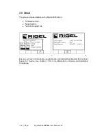
Page 30: ...des details on the Rigel 62353 Plus s Firmware version Serial Number Technical support line Ensure you have this information available when contacting Rigel Medical for Technical Support or Service Se...

Page 31: ...ions The following procedures describe the setup and completion of an automatic test sequence The steps are applicable to all available test sequences As example we describe a typical automatic test t...

Page 32: ...the database ie through the use of a serial number A representation is provided below Asset Trace Variables Asset ID database record Service code Site Location Make Model Description Serial Number Cli...

Page 33: ...ed labels and PC downloads that make it easier to schedule future work 3 4 Configure the Applied Parts To configure the Applied Parts press the button F1 Note that the Applied harness supplied with th...

Page 34: ...rate Applied Parts to be cnfigured as shown below When the configuration has been completed press the button F4 Pressing the button F3 would return to the previous screen and lose the settings 7 Retur...

Page 35: ...nu section 2 2 will not appear during the automatic tests A maximum of 40 individual entries are available for each Trace Variable Additional entries will overwrite on a first in first out basis When...

Page 36: ...ted See 2 1 6 for more information If one or more Visual tests result in a failure a Failure menu will appear Provided the test has Passed the next test will be the Earth Continuity Attention Ensure t...

Page 37: ...test fails the failure menu will be displayed See 4 1 2 Once the non powered tests have been completed the user is warned that the EUT is about to be switched on Warning never leave the earth bond or...

Page 38: ...after the EUT has been switched on The initial powered test is a load test The Rigel 62353 Plus will check for a short circuit EUT and ensure the applied load EUT is less than 16 A In case of a short...

Page 39: ...pply The Rigel 62353 Plus will automatically reverse the power and start the test sequence again In the semi automatic mode the user can determine when the measurements start In full automatic mode th...

Page 40: ...ical safety tests In this example we used a defib test Simply enter the reading from the defibrillator tester in the field provided Then determine whether the test has passed or failed Additional cust...

Page 41: ...to go to manual mode setup or data menu Continue with the next test F2 Automatically brings up the next test screen No further options or viewing of results available Options F3 To view the options me...

Page 42: ...estart Test Sequence Whole Test sequence Resume Test Skip the failed test End Test Sequence store result s and moves to comments field Abort Test Sequence no information stored return to home screen 3...

Page 43: ...also be chosen by pressing the button F4 and select Manual Mode from the list See below Do not connect any probe combination to voltages in excess of 30 V AC DC with respect to earth potential when p...

Page 44: ...press the button F4 to confirm The following manual mode screen appears The centre of the analogue bargraph indicates the limit value in this case 500 A Warning during many of the leakage tests the PR...

Page 45: ...s the button F3 Help is available by pressing the button F1 in the form of a schematic representation of the test Depending of the type of test the F2 key is either used to select the test class Class...

Page 46: ...e cross sectional area and length of cable and a new limit will be calculated This can be overridden by selecting the continuity limit from the list Press button F4 when complete button F3 will exit S...

Page 47: ...s are adequately insulated from earth Class I or the enclosure Class II During this test up to 500 VDC is applied between the earth pin and both the live and neutral pins of the appliance mains supply...

Page 48: ...lly used as part of MDA DB 9801 and IEC 62353 test routines Press the F1 button to obtain the schematic representation of this test Do not exceed the maximum permitted voltage of 30 V AC DC with respe...

Page 49: ...pressed 4 1 4 Insulation Resistance Applied Parts to Mains This test is applicable to Class I and Class II BF and CF equipment only typically used as part of IEC 62353 test routines Press the FI butto...

Page 50: ...ns Parts combined to real earth This test is applicable to Class I and Class II B BF and CF equipment This is an IEC 62353 test For a complete description of this test and applicable pass fail limits...

Page 51: ...her all 10 connections as part of this test For this reason the Applied Part configuration key is not available For Class I equipment use the earth bond lead from the black socket and connect to a con...

Page 52: ...es on precautions required for compliance with the relevant safety standards Do not exceed the maximum permitted voltage of 30 V AC DC with respect to earth potential Electric Shock danger Press butto...

Page 53: ...be For Class II devices use the earth bond lead from the black socket and connect to the enclosure preferably encapsulated within conductive foil Press the green START key to begin the test The test w...

Page 54: ...grouped together which eliminates the requirement to configure the Applied Parts as the Rigel 62353 Plus will short together all connections as part of this test For this reason the Applied Part confi...

Page 55: ...complete description of this test and applicable pass fail limits please see Appendix B Press the button F1 to obtain the schematic representation of this test Warning never leave the earth bond or a...

Page 56: ...e the earth bond lead from the black socket and connect to a conductive non earthed part For Class II devices use the earth bond lead from the black socket and connect to the enclosure preferably enca...

Page 57: ...e Settings menu For instructions on using this feature see 3 4 For both Class I and Class II appliances connect the Patient Connections or Applied Parts to the Applied Parts as per the configuration a...

Page 58: ...ket of the Rigel 62353 Plus To start the IEC lead test press the green START key The earth continuity resistance for the lead is measured using a 200mA test current The display indicates the highest r...

Page 59: ...55 Page Rigel Medical 62353 user Manual V1 4 The polarity test is performed at mains voltage The display shows the final result and the pass fail status See below...

Page 60: ...s its current capacity or delete the memory 5 1 View Data To view the stored data press the button F4 and select View Data from the menu The following screen provides an overview of all available reco...

Page 61: ...e the button F3 to view the Trace Variable and again to view the Applied Part setup See below In the Test Details screen press the button F4 to view the following options View Results will display the...

Page 62: ...main View Data screen press the button F1 Use the up down left and right keys to navigate this screen The default setting is which includes all records that Passed To search for more specific criteria...

Page 63: ...ons menu to allow the user to Download to PC Will download all records within the search criteria to the PC Delete Single Asset Will delete the single selected record Delete All Assets Will delete all...

Page 64: ...higher baud rate may result in incorrect data being transmitted The Rigel 62353 Plus is able to download in a number of formats to suit individual requirements These are CSV Full Comma Separate Value...

Page 65: ...d when the SSS format is activated on your device Select the Upload from PC option from the Data Transfer menu The Rigel 62353 Plus will now establish a connection to the PC as previously described in...

Page 66: ...een established the display will be as shown below Open the Data Transfer exe application on your PC and check that the Com Port is correct The baud rate will default to the correct value of 57600 If...

Page 67: ...ose down the Application and open the text file using word pad or equivalent The downloaded information can be used to clone other Rigel 62353 Plus s or modified to add additional trace variables Agai...

Page 68: ...Plus When the transfer is complete the Rigel 62353 Plus screen will display a message as shown below If the transfer is not successful check that the format of the configuration file exactly matches t...

Page 69: ...shows the number of asset records currently stored the remaining memory space number of assets deleted and number of assets in upload memory The nature of Flash memory is such that when records are de...

Page 70: ...ntegrity of the incoming earth TN supply see application note 0002 o Test may continue Check for over voltage on Live and Neutral wire o Test cannot continue Example of IT warning incoming earth fault...

Page 71: ...Plus is a rugged quality instrument However care should always be taken when using transporting and storing this type of equipment Failure to treat the product with care will reduce both the life of t...

Page 72: ...nhouse com CalibrationHouse 11 Bracken Hill South West Industrial Estate Peterlee County Durham SR8 2SW United Kingdom Prior to returning your unit for service please contact our service department to...

Page 73: ...s 0 1 ohms resolution Accuracy 3 of reading 10 m ohms Insulation Resistance Measurement EUT to Earth Ground EUT to AP AP to Ground Voltage 50 100 250 500 V DC 1mA Range low range 50V DC 0 01Mohms 10Mo...

Page 74: ...requency Test Current 3 5 mA current limited Measurement Range 4 A to 9999 A Measurement Resolution 1 A Measurement Accuracy 5 of reading 2 counts Measurement Type True RMS Measuring Device As per IEC...

Page 75: ...4 120 VAC 10 60Hz 1Hz USA model Battery 6 x 1 5V Alkaline AA Weight 1 6 kg including batteries Size L x W x D 270 x 110 x 75 mm 10 5 x 4 x 3 Operating conditions 0 C 40 C 0 90 RH NC Storage environme...

Page 76: ...then measured between the 2 leads Equipment Leakage The Equipment Leakage Test measures the total leakage deriving from the Applied Parts Enclosure and Mains Parts combined to real earth The Equipment...

Page 77: ...see Appendix C is positioned as part of a differential current measurement between the Live and neutral conductor Measurements are done in both polarities of the incoming mains with the protective ear...

Page 78: ...potential sinusoidal 50Hz signal 60Hz where this is the mains frequency The 1k measuring device equivalent to that used in the IEC 60601 standard see Appendix C is positioned directly after the voltag...

Page 79: ...mains frequency between the Applied Part and the Enclosure and Earth connection of the EUT connected to real Earth Leakage measurements to IEC 62353 are done using the RMS value instead of the separat...

Page 80: ...onnected together The test is performed using a current limited 3 5mA mains potential sinusoidal 50Hz signal 60Hz where this is the mains frequency The 1k measuring device equivalent to that used in t...

Page 81: ...s I Equipment Class II Equipment touch current 500 A 100 A 500 A 100 A 500 A 100 A Patient leakage current alternative method a c Class I II 5000 A 50 A Patient leakage current direct method a c Class...

Page 82: ...78 Page Rigel Medical 62353 user Manual V1 4 Appendix C IEC 60601 1 Measuring Device...

Page 83: ...Insulation AP to mains IEC 62353 Equipment Leakage Test Direct Alternative Differential AP Leakage Test Direct Alternative Load test IEC lead test Data View Data Data Transfer Download to PC Upload fr...

Page 84: ...ical 62353 user Manual V1 4 Appendix E Available Application Notes Please note that this section refers to our website where the most up to date application notes are available http www rigelmedical c...

Page 85: ...81 Page Rigel Medical 62353 user Manual V1 4 Appendix F Connection diagram AP lead...

Reviews: