-
45 -
|
Page Rigel Medical
62353+
user Manual V1.4
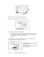
and set. Press the
button (F4) when complete. Pressing the
button (F3)
will exit the Settings mode without saving changes.
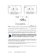
Press the class button (F2) to set the class of the appliance under test. For a class II
appliance the probe symbol will be displayed at the top of the LCD display.
For both Class I and Class II appliances, connect the Patient Connections or Applied
Parts to the Applied Part Module and fit the Appliance mains plug into the EUT outlet.
For Class 2 appliances only connect the Earth Bond lead to the appliance. Press the
green START key to begin the test. The test will run for the duration set or until the red
STOP key is pressed.
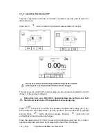
4.1.4 Insulation Resistance Applied Parts to Mains
This test is applicable to Class I and Class II BF and CF equipment only, typically used
as part of IEC 62353 test routines.
Press the FI
button to obtain the schematic representation of this test:
Do not exceed the maximum permitted voltage of 30 V AC/DC
with respect to earth potential! Electric Shock danger.
This test is used to verify that the Applied Parts are adequately insulated from the
mains parts.
During this test, up to 500 VDC is applied between all the Applied Parts
combined and both the live and neutral pins of the appliance mains supply
plug.
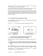
Press
button (F3) to set the Test Duration, Insulation test voltage (50 / 100 /
250 & 500 VDC) and Pass/Fail limit. Use the up, down, left and right keys to highlight
and set. Press the
button (F4) when complete. Pressing the
button (F3)
will exit Settings mode without saving changes.


