background image


Rigel SafeTest 60 Instruction Manual


– 

Revision 1.2


33


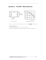
Appendix D  IEC 60601-1 Measuring Device 


Summary of Contents for SafeTest 60

Page 1: ...Innovating Together RIGEL SafeTest 60 electrical safety analyser Copyright 2016 SEAWARD GROUP Last Update 20th April 2016 Instruction Manual 410A568 Revision 1 2...

Page 2: ...cted by storage prior to receipt by the user We therefore recommend that the recalibration period be based on a 12 month interval from the first date the unit is placed in to service Date received int...

Page 3: ...rise yourself with the appropriate local separate collection system for electrical and electronic products or contact your local supplier for further information Please dispose of this product accordi...

Page 4: ...e declare under our sole responsibility that the product Rigel SafeTest 60 Electrical Medical Safety Analyser Conforms with the relevant Directives and conformity is indicated by the symbol i e Confor...

Page 5: ...EAKAGE testing_________________________________________ 17 7 IEC 61010 TOUCH LEAKAGE VOLTAGE testing _______________________ 19 8 Minimise your power breaks in IEC 60601____________________________ 21...

Page 6: ...II 300 V AC DC Do not touch test probes beyond the hand barrier on the test probe The SafeTest 60 may apply high voltage or mains power to the appliance under test Do not touch conductive parts of th...

Page 7: ...ull manual control offers the benefit of executing only those specific tests that are required and provide the user with full control of the power cycles making testing simple easy and fast An automat...

Page 8: ...on 1 2 7 1 3 Interfaces Earth bond and Enclosure leakage probe Mains inlet 90 264 VAC 48 64Hz Point to point auxiliary probe EUT socket 90 264 VAC 48 64Hz Mains START STOP REVERSED keys Single Fault O...

Page 9: ...o help guide the user through the different test steps Below are of some of the icons used in the Rigel SafeTest 60 Select EARTH BOND TESTING Select LEAKAGE TESTING Select INSULATION TESTING Select PO...

Page 10: ...500VDC supplied to EUT Select Earth leakage in IEC60601 setting Select Enclosure leakage in IEC60601 setting Select Touch Leakage in IEC61010 setting Select Touch Voltage in IEC61010 setting Open EART...

Page 11: ...h ON To switch on the Rigel SafeTest 60 please insert the mains cable to the power inlet the SafeTest 60 will automatically power up in the HOME SCREEN 2 1 Setting your language and preferred test sta...

Page 12: ...SafeTest 60 will store the most recent settings in the SETTINGS MENU From the home screen select the required test To select EARTH BOND TESTING To select LEAKAGE TESTING To select INSULATION TESTING T...

Page 13: ...point Do not exceed the maximum permitted voltage of 30 V AC DC with respect to earth potential Electric Shock danger To compensate for the test cable resistance connect the test cable between the bl...

Page 14: ...st press the button on the front panel The test will run until the button is pressed To apply mains in REVERSED POLARITY and START the test press the button on the front panel The test will run until...

Page 15: ...selected fault conditions Connection between EUT and SafeTest 60 ENCLOSURE LEAKAGE ALL Applied Parts Leakage Current Type NC SFC Earth Leakage 3rd edition 5mA 10mA Earth Leakage General 0 5mA 1mA Enc...

Page 16: ...e test press from HOME screen to enter LEAKAGE test If the required test standard needs to change please press HOME and see 2 1 To apply mains voltage in NORMAL POLARITY and START the test press the b...

Page 17: ...to test to IEC 62353 the SINGLE FAULT buttons and are deactivated in order to perform the test as per IEC 62353 requirements Connection between EUT and SafeTest 60 EQUIPMENT LEAKAGE IEC 62353 Current...

Page 18: ...in NORMAL POLARITY and START the test press the button on the front panel The test will run until the button is pressed To apply mains in REVERSED POLARITY and START the test press the button on the...

Page 19: ...the and buttons on the front panel opens the EARTH fault condition relay whilst the opens the NEUTRAL fault condition relay The leakage screen will indicate the current state of the selected fault con...

Page 20: ...TY and START the test press the button on the front panel The test will run until the button is pressed To apply mains in REVERSED POLARITY and START the test press the button on the front panel The t...

Page 21: ...use the and buttons on the front panel opens the EARTH fault condition relay whilst the opens the NEUTRAL fault condition relay The leakage screen will indicate the current state of the selected fault...

Page 22: ...NORMAL POLARITY TESTING POWER UP 1 EARTH LEAKAGE Normal Supply 2 ENCLOSURE LEAKAGE Normal Supply Earth Closed 3 ENCLOSURE LEAKAGE Normal Supply Earth OPEN NORMAL POLARITY TESTING POWER DOWN 4 ENCLOSU...

Page 23: ...both the live and neutral pins of the EUT The INSULATION VOLTAGE will be applied between L N to EARTH for class 1 equipment or L N to the black socket for class 2 equipment Connection between EUT and...

Page 24: ...eturn to the HOME screen Select will perform a standard insulation test Connect the POINT TO POINT probes between the BLACK and GREEN socket on the back panel The EUT socket will power up during leaka...

Page 25: ...d from earth Secondary earth warning To perform a valid test the secondary earth must be removed Testing with a secondary earth will lead to invalid readings as the leakage current will flow through t...

Page 26: ...2 25 12 About From the HOME SCREEN select SETTINGS then the key to view the firmware and hardware information Firmware version Serial Number Ensure you have this information available when contacting...

Page 27: ...reduce both the life of the instrument and its reliability If the Rigel SafeTest 60 is subject to condensation allow the Analyser to completely dry before use Always check the Rigel SafeTest 60 and a...

Page 28: ...t our service department to obtain a Returns Number By obtaining a Returns Number your service request can be booked in advance thus reducing the down time of your equipment When asking for a Returns...

Page 29: ...uipment Leakage Direct IEC AAMI 60601 Earth Enclosure Leakage NFPA 99 Ground Chassis Leakage IEC 61010 Touch Leakage Touch Voltage Test Voltage Mains Supply Voltage Measuring Range 0 1 9999 A 0 1 8000...

Page 30: ...L x W x D 225 x 150 x 100mm 9 x 6 x 4 Environmental Operating temperature 0 to 40 C Humidity 0 98 Relative humidity non condensating Storage temperature 10 to 50 C Altitude 0 2000m Ingress Protection...

Page 31: ...1000 A Enclosure Leakage 100 A 500 A 100 A 500 A 100 A 500 A Patient Leakage dc 10 A 50 A 10 A 50 A 10 A 50 A Patient Leakage ac 100 A 500 A 100 A 500 A 10 A 50 A Patient Leakage F Type NA NA NA 5000...

Page 32: ...pment leakage direct or differential method Class I Equipment Class II Equipment touch current 500 A 100 A 500 A 100 A 500 A 100 A Patient leakage current alternative method a c Class I II 5000 A 50 A...

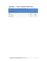
Page 33: ...0 Instruction Manual Revision 1 2 32 Appendix C Pass Fail limits of IEC 61010 EARTHBOND TEST LIMIT NO CURRENT SPECIFIED IN 61010 INCLUDING POWER CORD 0 2 Tests NC SFC Touch Leakage 500 A 3500 A Touch...

Page 34: ...Rigel SafeTest 60 Instruction Manual Revision 1 2 33 Appendix D IEC 60601 1 Measuring Device...

Reviews: