6 |
P a g e
R i g e l M e d i c a l U n i - T h e r m u s e r M a n u a l V 1 . 0
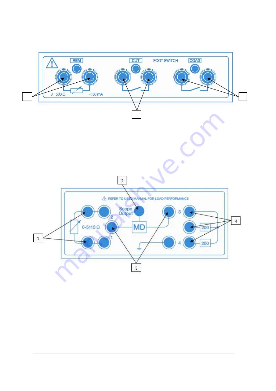
Front panel
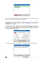
Side panel
*Note; The scope output (SMB connector) provides an 10kV isolated waveform
monitoring output however the scope output is not calibrated.
1. REM output connection (Black)
2. CUT footswitch control output (Yellow)
3. COAG footswitch control output (Blue)
1. Variable load bank connections (Red
& Black)
2. Oscilloscope output*
3. Measuring Device connections
(White)
4. HF Leakage connections
1
2
3


