4 How to Use
4-6. How to wire
- 19 -
NOTE
The following table shows an example of overall outer diameters of cables. Use them for reference.
The overall outer diameters must be checked because they somewhat vary between manufacturers.
Number of core
EM CCE/F 1. 25 mm
2
EM CCE/F 2 mm
2
2 ø9.4
ø10.5
3 ø9.9
ø11.0
4 ø11.0
ø12.0
5 ø11.5
ø13.0
6 ø12.5
ø14.0
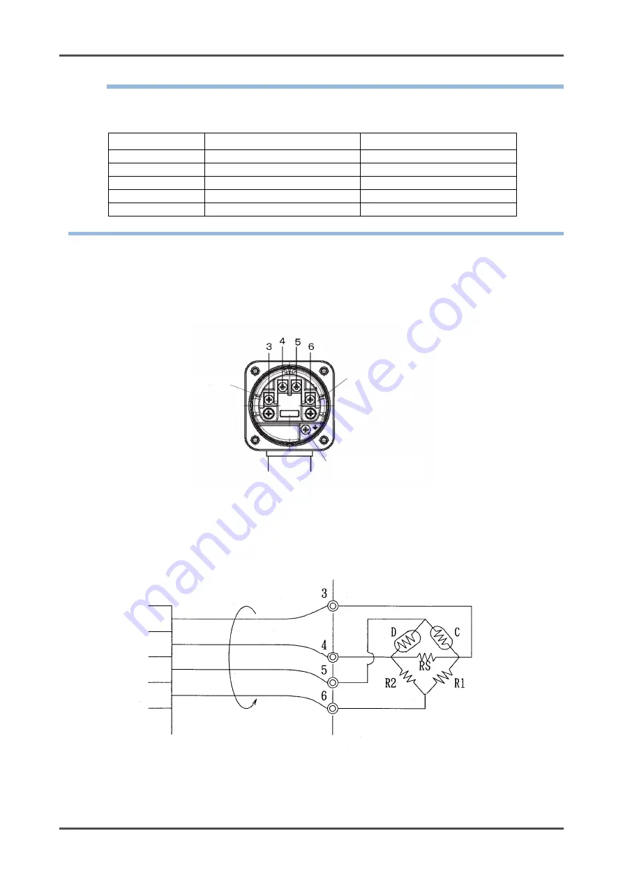
(1) The numbers 3, 4, 5 and 6 are shown on the terminal plate of the detector head. Perform wiring in the
correct wiring order according to the following connection diagrams.
When attaching the lid of the detector head, be careful not to squeeze the cable. (To make the work
easier, fasten the cable gland temporarily to the detector head.)
Screw size: M4
<Wiring Example>
Indicator/alarm unit
terminal plate
GP-5001 etc.
Detector head terminal
plate
GD-A80-70
12
11
13
14
15
EM CCE/F, 4-core
1. 25 or 2 mm
2
Internal grounding
terminal
Cable
connection
terminal plate
M4 screw


