background image

9 Product Specifications


9-2. Detection principle 


- 32 - 


9-2. Detection principle 

 
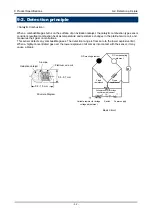
<Catalytic Combustion> 
 
When a combustible gas burns on the surface of an oxidation catalyst, the catalytic combustion type sensor 
considers resultant combustion heat as temperature and resistance changes in the platinum wire coil, and 
measures their gas concentrations. 
This sensor detects any combustible gases. The detection range is from zero to the lower explosive limit. 
When a highly-concentrated gas over the lower explosive limit comes into contact with the sensor, it may 
cause a break. 


0.8 - 1.0 mm 

Basic Circuit 

0.5 - 0.7 mm 

Structure Diagram

Oxidation catalyst 

Alumina 

Variable resistor for bridge 

voltage adjustment 

Platinum wire coil

Power supply 

Fixed 

resistance 

Variable resistor for bridge

equilibrium adjustment 

D: Detecting element 

C: Compensating   

element 

Fixed 

resistance 

Switch

Summary of Contents for GD-A80 Series

Page 1: ...PT2E 1856 Fixed Combustible Gas Detector Head GD A80 Series GD A80 70 Operating Manual...

Page 2: ...d In facilities compliant with the High Pressure Gas Safety Act an alarm setting below our standard alarm setpoint may trigger a false alarm 3 This is a safety unit not a control unit 4 If silicon or...

Page 3: ...12 4 3 Precautions for system designing 13 4 4 How to install 15 4 5 Installation procedure 16 4 6 How to wire 18 5 How to Operate 5 1 Preparation for start up 21 5 2 How to start the detector 21 5 3...

Page 4: ...ector is a safety unit not an analyzer or densitometer which performs quantitative qualitative analysis measurement for gases Please fully understand the features of the detector before using it so th...

Page 5: ...some specification depends on standard and explosion proof certificate Please confirm the detector specification before using Please refer Declaration of Conformity that is at the end of this manual...

Page 6: ...rting the detector check the protective functions for defects When seeming defects are found in the protective functions such as protective grounding do not start the detector Zero adjustment in the a...

Page 7: ...sed in a place where it disturbs nothing Do not disassemble modify the detector Disassembling modifying the detector will invalidate the warranty of the performance Please use the detector properly in...

Page 8: ...that ensures product performance For the operating temperature see 9 Product Specifications Specific conditions of X mark Regarding ATEX specification the measuring function according to Annex II par...

Page 9: ...dard JNIOSH TR NO 43 2008 The ambient temperature range that can maintain explosion protection and is not operating temperature range that ensures product performance For the operating temperature see...

Page 10: ...in unit and standard accessories Main Unit including a cable gland Side view Front view Fixing bracket Cable gland Hexagon socket set screw Hexagon socket head bolt with drop prevention mechanism Exte...

Page 11: ...1 one Rubber seal ID 13 mm one Washer ID 12 mm 1 one Washer ID 14 mm one Eccentric washer ID 11 8 mm 1 one Eccentric washer ID 12 8 mm one Hex key wrench 2 1 Attached to the suction type only 2 Instal...

Page 12: ...see 6 1 Maintenance intervals and items 4 2 Precautions for installation sites Do not install the detector in a place with vibrations or shocks The detector consists of sensitive electronic parts The...

Page 13: ...ery which is not properly grounded Before installing the detector in machinery the machinery must be grounded properly Do not install the detector in a place where interference gases exist around it T...

Page 14: ...talling a lightning arrester before the field devices and central processing equipment For information on how to use a lightning arrester please contact the manufacturer Grounding In addition to light...

Page 15: ...tor cannot be performed or where handling the detector involves dangers Regular maintenance of the detector must be performed Do not install the detector in a place where the machinery must be stopped...

Page 16: ...F etc For the wiring method see 4 6 How to wire Diffusion type NOTE Maximum surface roughness of the enclosure face for sealing is Ra6 3 m Hexagon socket head bolt M5 x 20 Washer Pressure proof packin...

Page 17: ...for the installation environment installation direction etc Use a square drip proof cover for an inferior environment condition such as a place with a risk of water splash Use a round drip proof cover...

Page 18: ...aw the cable to the detector by the means that do not impair the explosion proof performance Connect the power to the indicator alarm unit after all wiring work is completed Wiring with the power conn...

Page 19: ...3 4 5 and 6 are shown on the terminal plate of the detector head Perform wiring in the correct wiring order according to the following connection diagrams When attaching the lid of the detector head...

Page 20: ...erformance When wiring is completed check for wrong wiring once again before turning on the power If the power is turned on with wrong wiring sensor disconnection will occur and the unit will become u...

Page 21: ...icator alarm unit 5 3 How to detect Turn on the power switch of the indicator alarm unit Gas detection starts after the initial clear 5 4 How to exit Turn off the power switch of the indicator alarm u...

Page 22: ...r more for every six months to maintain the performance as a safety unit Maintenance item Maintenance content Daily maintenance Monthly maintenance Regular maintenance Power lamp check Check that the...

Page 23: ...alarm test function Checks the alarm lamp Checks ALM activation Checks the external alarm Checks the activation of the external alarm such as a buzzer Span adjustment Performs the span adjustment by u...

Page 24: ...ing to zero at the indicator alarm unit side under the condition that no gas is present around the detection point If a gas is present around the detection point collect fresh air in a gas sampling ba...

Page 25: ...adjustment NOTE The span adjustment requires dedicated tools We recommend the adjustment be performed by RIKEN KEIKI CAUTION Before starting the span adjustment provide the detector with the calibrat...

Page 26: ...rthest from the cable inlet see figure below insert it lightly shallowly to the socket in the hole of the main unit Then push the gas sensor to insert it deep in the socket 5 Put the sensor guard over...

Page 27: ...ation must be checked after replacement by our service engineer For the stable operation of the detector and safety ask our service engineer to take care of replacement of the part Request RIKEN KEIKI...

Page 28: ...dures to relocate the detector or use it again When the detector is relocated select a new place in accordance with 4 2 Precautions for installation sites and 4 4 How to install For information on wir...

Page 29: ...ke a remedial measure i e taking actions the same as those for the gas alarm Environmental changes Perform zero adjustment A gas alarm is triggered despite of no gas leak and no other abnormalities at...

Page 30: ...2 for mounted 13 for attached Operating temperatures 10 100 At a constant condition 40 70 At a constant condition Operating humidities Below 95 RH Non condensing Structure Wall mounting type 2B 50A pi...

Page 31: ...for attached Operating temperatures 10 100 At a constant condition 40 70 At a constant condition Operating humidities Below 95 RH Non condensing Structure Wall mounting type 2B 50A pipe attachable Ex...

Page 32: ...entrations This sensor detects any combustible gases The detection range is from zero to the lower explosive limit When a highly concentrated gas over the lower explosive limit comes into contact with...

Page 33: ...put from the detector head fluctuates for a while after turning on the power This is a function to prevent triggering alarm during that time Full scale Maximum value of the detection range LEL A unit...

Page 34: ......

Reviews: